Table of Contents
- Information Gain: The Civil Interface Is a Purchase Decision
- Start With a Controlled Machine-and-Civil Interface Package
- Define the Foundation Boundary Before You Price the Plant
- Do Not Use Generic Foundation Dimensions or Bolt Patterns
- Make Access, Lifting, and Drainage Part of the Layout
- Coordinate Installation Sequence, Not Just the Final Layout
- Acceptance Records That Prevent an Argument Later
- Buyer Checklist Before You Release Civil Work
- What to Send for a VSI Foundation and Installation Proposal
- FAQ
- Does every VSI crusher need a concrete foundation?
- Can I build the foundation before choosing the final VSI model?
- What load data should the crusher supplier provide?
- Should the VSI foundation be connected to conveyor and screen foundations?
- Why do drainage and access matter to VSI installation?
- Can I set anchor bolts from a preliminary GA drawing?
- Who is responsible for crusher foundation design?
- What should be checked before first material is fed to the VSI?
VSI Crusher Foundation and Installation: Civil Work Checklist
A VSI crusher foundation should be released for construction only after the selected machine supplier and the project’s civil, structural, electrical, and installation teams agree on one controlled interface package. That package needs more than a general arrangement drawing: it should identify the exact machine footprint, support reactions and dynamic assumptions, anchor or hold-down detail, elevations, maintenance and lifting clearances, conveyor interfaces, drainage, cable routing, and acceptance checks. Do not copy a foundation from a visually similar crusher. A change in rotor, drive, support frame, feed arrangement, or adjacent equipment can change the civil and installation scope. Use the supplier’s current model-specific data and a qualified local engineer before concrete work begins.
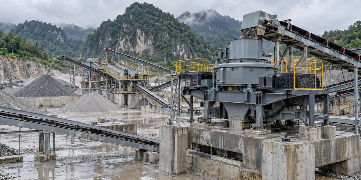
Information Gain: The Civil Interface Is a Purchase Decision
Many crusher guides describe the machine, feed, and capacity. The expensive risk often occurs earlier: a buyer releases civil work from a preliminary layout, then discovers that final supports, bolts, platforms, cable routes, lifting access, or conveyor elevations do not match the selected equipment. This guide focuses on that handoff: what to request before foundations are built and what to check before a delivery date becomes a site installation date.
Start With a Controlled Machine-and-Civil Interface Package
The foundation design belongs to the project engineer, using current supplier data for the actual selected machine. A general brochure, a drawing from a different model, or a drawing marked preliminary is not a construction release. Ask the supplier to identify the revision and assumptions behind every installation input.
| Information to obtain | Why it matters before civil work | Buyer check |
|---|---|---|
| Approved general arrangement | Sets envelope, centerlines, support locations, elevations, and interfaces | Confirm model, configuration, revision, units, and orientation |
| Static and operating support data | Lets the structural engineer assess supports and project design cases | Ask what startup, shutdown, maintenance, and upset assumptions are included |
| Anchor and base-interface detail | Controls setting-out, embeds, grout interface, and tolerance | Do not cast bolts or pockets until the final detail is issued |
| Conveyor and chute interfaces | Prevents incompatible elevations and inaccessible transfer points | Verify material path, inspection access, liners, and movement requirements |
| Maintenance and lifting requirements | Ensures the installed plant can be safely serviced | Confirm routes, lifting points, lifting envelope, and laydown space |
| Electrical, controls, and services list | Avoids late conflicts with slabs and structures | Define scope boundaries and routing before construction closes them |
The supplier should label what it provides as an equipment interface and what must be designed locally. Soil investigation, foundation sizing, reinforcement, drainage capacity, crane selection, electrical protection, and site safety are project-specific scopes. Do not turn a vendor layout into an unsupported civil design.
Define the Foundation Boundary Before You Price the Plant
The visible VSI is only part of the installation. The civil scope must also make room for feed and discharge chutes, support steel, the drive and guards, inspection openings, platforms, return conveyors, dust connections where used, and safe walkways. A low initial civil quote can become costly if it omits interfaces needed to operate and maintain the system.
- Fix material-flow elevations. Confirm the upstream screen or bin discharge, crusher inlet and discharge, final screen, return path, and stockpile conveyors in one coordinate system.
- Separate and coordinate structures. Determine which supports belong to the VSI, conveyors, and screen packages, and whether movement or vibration assumptions need coordination.
- Reserve maintenance space. Check safe isolation, rotor or wear-part work, liner access, lifting, and a controlled route for removed components.
- Plan water and fines management. Grade the area and provide drainage and cleaning access so runoff does not block essential routes.
- Freeze openings before pour. Coordinate cable trenches, sleeves, earthing points, drains, embeds, and access openings in the issued-for-construction package.
Use the VSI crusher commissioning checklist after—not instead of—the civil and installation acceptance record.
Do Not Use Generic Foundation Dimensions or Bolt Patterns
There is no reliable universal foundation thickness, reinforcement schedule, bolt size, or concrete grade for a VSI crusher. The right design depends on the selected machine, support frame, dynamic behavior, mass, connected equipment, geotechnical conditions, local code, and site design basis. The buyer obtains controlled engineering inputs; the civil engineer designs the site foundation; the supplier defines the machine interface and approved installation requirements.
- Is this the final drawing revision for the quoted VSI, drive, support frame, and chamber arrangement?
- Which support reactions and operating cases are included, and which require local review?
- Are anchors, pockets, embeds, leveling/grout interfaces, tolerances, and tightening sequence specified?
- What is the approved relationship between crusher, feed, discharge, screen, and return-conveyor structures?
- Does the drawing show every removable guard, access door, service point, and lifting envelope?
Make Access, Lifting, and Drainage Part of the Layout
| Area | Agree before construction | Common late-stage failure |
|---|---|---|
| Maintenance platform | Guarded routes, stairs, landings, clearances, inspection points | Platform blocks a removable component or chute door |
| Lifting and laydown | Approved lifting points, device envelope, route, rated support, staging | Part can be removed but has no controlled path or safe staging area |
| Drainage and cleaning | Falls, channels, collection, cleanout access | Water and fines accumulate around supports, cables, or walkways |
| Cables and controls | Tray route, isolation, earthing, sensors, lighting, testing access | Finished concrete is cut because sleeves were omitted |
| Conveyor interfaces | Chute support, inspection space, guards, belt access and tolerance | Fit-up creates spillage, inaccessible liners, or blocked walkways |
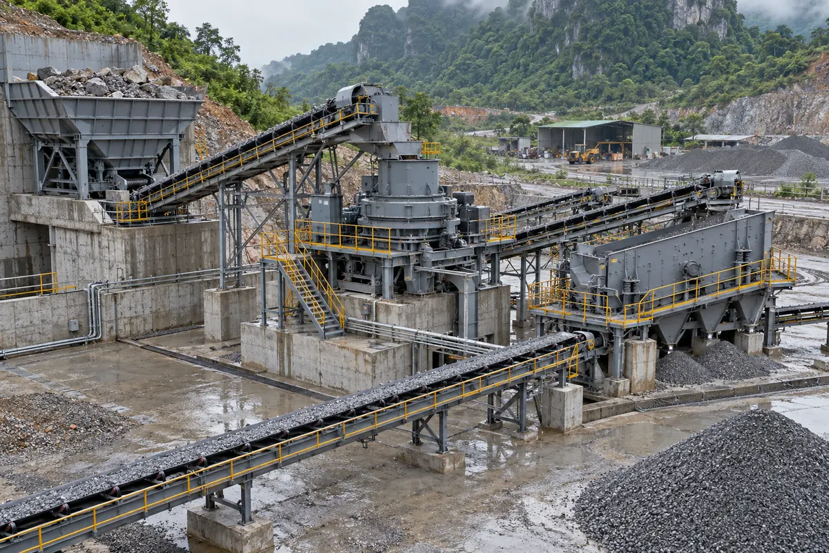
Coordinate Installation Sequence, Not Just the Final Layout
Follow the supplier manual and project method statement, but coordinate a sequence that verifies issued-for-construction drawings, survey control, foundations, embeds, equipment identity, approved lifting instructions, alignment, interfaces, guards, services, and no-load checks before material processing. Do not improvise shims, anchors, grout, drive adjustments, structural modifications, or changes to rotor speed, pulleys, electrical protection, or guards to solve a fit-up issue.
Stable product performance also requires controlled circuit conditions. The VSI feed-size control guide helps separate feed and screening issues from installation observations.
Acceptance Records That Prevent an Argument Later
Collect approved drawings, revision logs, survey/as-built records, civil and installation inspections, delivery condition photos, serial numbers, packing checks, approved installation/alignment/guard/drive/lubrication/electrical records, and photos of completed drains, access, lifting provisions, guards, cable routes, and material path. They provide a baseline for commissioning and later troubleshooting.
If an operator later sees unstable product or elevated bearing temperature, review the whole controlled system rather than assuming a single observation proves a foundation fault. The bearing temperature and lubrication guide explains why operating conditions and approved limits must be treated together.
Buyer Checklist Before You Release Civil Work
- Exact machine configuration and current drawing/data revision are identified.
- Civil/structural engineer has selected-machine interfaces and site information.
- Supports, conveyors, chutes, screens, and return paths share one elevation and centerline system.
- Anchor, embed, tolerance, leveling/grout, and installation data are final—not copied from another machine.
- Access, isolation, lifting, laydown, drainage, lighting, cables, earthing, and cleaning scope have owners.
- Supplier supply, civil work, installation, electrical/controls, and commissioning support are separated in the proposal.
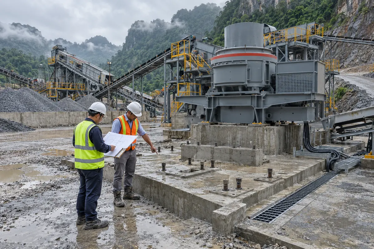
What to Send for a VSI Foundation and Installation Proposal
Send the raw material, feed size, target output sizes, required capacity, operating hours, process flow or preliminary layout, site photos and survey information, elevation constraints, available power, local civil/geotechnical information, proposed installation access, lifting limitations, drainage conditions, delivery destination, schedule, and budget range. Also state whether you need supplier drawings, structural load/interface data, installation supervision, commissioning support, or a complete equipment-and-steel scope.
FAQ
Does every VSI crusher need a concrete foundation?
The support arrangement depends on the selected machine and plant design. A stationary VSI commonly needs an engineered permanent support system, while mobile equipment uses its designed chassis and setup method. Use current supplier documents and a qualified engineer.
Can I build the foundation before choosing the final VSI model?
Avoid releasing final foundation work before final approved interface data is available. Supports, embeds, elevations, and access should be frozen from the selected equipment package.
What load data should the crusher supplier provide?
Ask for current model-specific general arrangement, support/interface data, operating assumptions, anchor detail, tolerances, connected-equipment interfaces, and maintenance/lifting requirements.
Should the VSI foundation be connected to conveyor and screen foundations?
That is a project engineering decision based on selected structures, operating loads, movements, and site conditions.
Why do drainage and access matter to VSI installation?
They control safe inspection, cleaning, isolation, service, and removal of components without standing water, fines buildup, or restricted routes.
Can I set anchor bolts from a preliminary GA drawing?
No. Use the approved final detail for the exact machine and verify its revision, orientation, dimensions, tolerances, embedded items, and installation method before concrete placement.
Who is responsible for crusher foundation design?
The project civil or structural engineer designs the foundation. The equipment supplier provides machine interface data and approved installation requirements.
What should be checked before first material is fed to the VSI?
Complete approved mechanical, guarding, electrical, lubrication, controls, access, and no-load checks, then establish a controlled operating baseline under the commissioning procedure.