


Table of Contents
- Maximizing Aggregate Production with the allis chalmers crusher #248; 3 pies
- Optimizing Crushing Efficiency: Key Advantages of the 3-Pie Design
- Technical Specifications and Performance Metrics for the #248 Crusher
- Durability and Reliability: Built for Long-Term Mining and Quarry Operations
- Integration and Compatibility with Existing Crushing Systems
- Support and Maintenance: Ensuring Peak Performance and Uptime
- Frequently Asked Questions
- What is the recommended replacement cycle for the main wear parts (mantle and concave)?
- How does the crusher adapt to processing ores of varying hardness (e.g., from limestone to taconite)?
- What are the critical specifications for the lubrication system to prevent bearing failure?
- What procedures control excessive vibration and ensure stable operation?
- How is the hydraulic system adjusted for clearing tramp metal and setting changes?
- What is the best practice for inspecting and maintaining the drive assembly (countershaft and pinion)?
In the world of industrial machinery, few names command as much respect as Allis-Chalmers, a legacy built on robust and innovative equipment. Among its storied lineup, the Allis-Chalmers Crusher #248, specifically the 3-pies (3-foot) model, stands as a testament to mid-century engineering excellence. This cone crusher was more than just a piece of heavy machinery; it was a pivotal solution for aggregate production, renowned for its durable construction and reliable crushing capabilities. Its design principles influenced generations of equipment, making it a significant chapter in the history of mineral processing. Understanding this machine offers a fascinating glimpse into the evolution of crushing technology and the enduring impact of a true industry pioneer.
Maximizing Aggregate Production with the allis chalmers crusher #248; 3 pies
The Allis Chalmers #248 3′ crusher is engineered for primary and secondary reduction of hard, abrasive materials. Its robust mechanical design and material selection directly determine throughput, product gradation, and operational longevity in demanding aggregate and mining applications.
Core Mechanical Advantages for Production
- Heavy-Duty Manganese Steel Wear Components: The mantle and concave are cast from work-hardening Hadfield manganese steel (typically 11-14% Mn). Under impact loading, the austenitic matrix deforms, increasing surface hardness from ~200 HB to over 500 HB, providing exceptional resistance to abrasion and gouging in silica-rich aggregates and hard ores.
- Optimized Crushing Chamber Geometry: The 3-foot diameter chamber with a non-choking, curved concaves design promotes inter-particle crushing. This creates a rock-on-rock action that improves reduction efficiency, increases yield of in-spec product, and minimizes wear metal contamination.
- Hydraulic Adjustment and Clearing: The hydraulic adjustment system allows for precise closed-side setting (CSS) changes under load to maintain product size control. The hydraulic clearing function rapidly lowers the mantle to pass tramp iron or uncrushable material, reducing downtime and risk of mechanical damage.
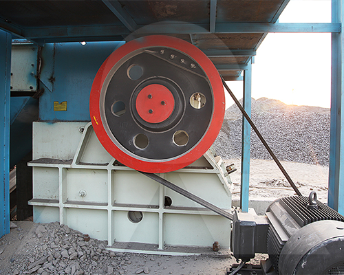
- Spiral-Bevel Gear & Pinion Drive: The high-torque drive system provides consistent power transmission for high inertia crushing. Precision-machined gearing ensures reliable performance at the crusher’s designed horsepower rating, supporting sustained high-tonnage output.
Technical Specifications & Performance Parameters
| Parameter | Specification / Capacity |
|---|---|
| Nominal Feed Opening | 3 inches (76 mm) |
| Maximum Recommended Feed Size | 2.5 inches (64 mm) |
| Approximate Weight | 12,000 lbs (5,443 kg) |
| Drive Power Requirement | 100 – 125 HP (75 – 93 kW) |
| Typical Capacity Range (TPH) | 45 – 180 TPH |
| Material Hardness Adaptability | Suitable for compressive strengths up to 350 MPa (e.g., granite, basalt, quartzite) |
Maximizing Output: Operational Guidelines
Achieving rated capacity depends on correct feed and operational discipline. Feed material must be properly sized to match the crusher’s intake dimensions. A continuous, well-distributed feed across the full chamber circumference is critical to maintain uniform wear and full crushing force. The closed-side setting must be monitored and adjusted to compensate for mantle and concave wear, which directly impacts product gradation. Pairing the crusher with a correctly sized and regulated feed system—such as a vibrating grizzly feeder—is essential to prevent choking and optimize power draw.
Maintenance is predictive, not reactive. Regularly monitor manganese wear patterns; uneven wear indicates incorrect feed distribution or crusher operation. Bearing temperature and lubrication system integrity are primary indicators of mechanical health. The design allows for liner changes without removing the mantle, streamlining planned maintenance shutdowns. Adherence to these technical and procedural standards ensures the #248 3′ crusher delivers maximum availability and return on investment in continuous production circuits.
Optimizing Crushing Efficiency: Key Advantages of the 3-Pie Design
The 3-pie mantle design is a critical engineering feature for optimizing wear life and throughput in secondary and tertiary crushing circuits. Its primary function is to distribute wear more evenly across the crushing surface, directly countering the localized, high-wear patterns inherent in traditional two-piece designs. This is achieved through a segmented geometry that allows for independent wear progression in the upper, middle, and lower crushing zones.
Core Functional Advantages:
- Optimized Wear Profile Management: The three distinct segments create a self-compensating wear pattern. As the upper section wears and the feed throat opens, the middle and lower sections maintain a tighter setting, preserving product gradation and crusher throughput for significantly longer periods compared to a two-piece mantle.
- Increased Manganese Utilization: The segmented design allows for targeted thickness and alloy specification in each pie section. Upper sections, facing initial impact and abrasion, can be cast from a tougher, more impact-resistant grade of Austenitic Manganese Steel (AMS), such as a modified Grade C with enhanced yield strength. Lower sections, subject to higher compression forces, can utilize a work-hardening AMS grade to maximize service life. This strategic material use increases total tons crushed per mantle set by 25-35%.
- Operational Flexibility & Reduced Downtime: Individual “pie” sections can be rotated or replaced independently. This permits crusher operators to address specific wear zones without a full mantle change, drastically reducing liner inventory costs and planned maintenance downtime. The ability to perform a partial change-out during a scheduled maintenance stop is a key operational USP.
- Consistent Product Gradation: By maintaining a more controlled crushing cavity geometry throughout the wear cycle, the 3-pie design minimizes product size drift. This stability is critical for downstream process efficiency in grinding circuits, ensuring consistent feed to SAG or ball mills.
- Adaptability to Ore Characteristics: The design philosophy allows for customization of the mantle profile for specific applications. For hard, abrasive taconite or iron ore, a steeper profile can be specified to enhance nip angle and crushing force. For softer, sticky materials, a flatter profile improves throughput and reduces packing.
Technical Specifications & Performance Data
| Parameter | Specification / Advantage | Operational Impact |
|---|---|---|
| Design Standard | Engineered to exceed ISO 13533:2001 (Drilling and production equipment) and CE requirements for structural integrity. | Ensures reliability under dynamic loading and cyclic stresses in 24/7 mining operations. |
| Material Grade | Premium Austenitic Manganese Steel (AMS), typically Grade B-3 or proprietary modified alloys with precise heat treatment. | Provides optimal balance of initial toughness, work-hardening capability, and abrasion resistance. |
| Typical Capacity Range | 150 – 600 TPH, dependent on closed-side setting, feed size, and ore work index (Wi). | Designed for mid-to-high volume secondary/tertiary stations in aggregate and hard rock mining. |
| Primary Application | Optimized for processing abrasive materials with a compressive strength up to 350 MPa (e.g., granite, basalt, quartzite). | The wear-management design directly counters the high abrasion wear from siliceous ores. |
| Key Metric: Wear Life Increase | 25-35% longer service life compared to equivalent 2-piece mantle designs in identical duty. | Directly lowers cost per ton (CPT) for wear components and reduces annual liner change-out frequency. |
The engineering rationale is straightforward: by dividing the mantle into three strategic wear zones, the design transforms a consumable component into a performance-management system. It directly addresses the fundamental economic drivers of crushing—maximizing throughput between changes and minimizing total cost of ownership through superior material utilization and operational flexibility. This makes it a calculated investment for operations focused on process stability and long-term cost per ton metrics.
Technical Specifications and Performance Metrics for the #248 Crusher
Primary Crushing Chamber & Mantle Configuration
The #248 crusher is engineered for secondary and tertiary reduction of hard, abrasive ores. Its 3-foot (914.4 mm) nominal feed opening is paired with a steep, non-choking mantle profile. This geometry optimizes the inter-particle compression crushing action, critical for generating a consistent, cubical product while minimizing slabby output.
Core Component Material Specifications
- Mantle & Concaves: Fabricated from ASTM A128 Grade B-3 (approx. 12-14% Manganese Steel) in standard configuration. For extreme abrasion with moderate impact (e.g., taconite, granite), Grade C (approx. 1.2% Carbon, 12% Mn) offers superior work-hardening. Optional alloys, such as ASTM A514 T1 or proprietary martensitic steels with chromium carbides, are available for highly abrasive, low-impact applications.
- Main Shaft & Eccentric: The forged steel main shaft (typically AISI 4340 or equivalent) is heat-treated for high yield strength and fatigue resistance. The eccentric assembly is a high-strength cast iron or nodular iron casting, precision-machined to maintain bearing alignment under full load.
- Frame & Countershaft Box: The main frame is a heavy-section, weldment of ASTM A36 steel, with integral reinforcing ribs at all high-stress points. The countershaft box is a stress-relieved steel casting, ensuring permanent alignment of the countershaft bearings.
Performance Metrics & Operational Parameters
| Parameter | Specification / Metric | Notes |
|---|---|---|
| Nominal Feed Opening | 3 ft (914.4 mm) | Accepts feed sizes up to 85% of gape, depending on mantle setting. |
| Recommended Max Feed Size | 6 in (152 mm) | For optimal capacity and liner life. |
| Closed Side Setting (CSS) Range | 0.5 in – 2.5 in (13 mm – 64 mm) | Finer settings for tertiary crushing, wider for secondary duty. |
| Gross Power Rating | 150 – 200 HP (112 – 149 kW) | Dependent on drive sheave configuration and motor slip. |
| Weight (Crusher Only) | ~27,000 lbs (12,247 kg) | Approximate, varies with optional equipment. |
| Thrust Bearing | Bronze-faced, self-aligning type. | Designed for continuous high-load operation without external cooling. |
Capacity & Throughput (TPH)
Throughput is non-linear and highly dependent on ore characteristics, CSS, and chamber geometry. As a guideline:
- Secondary Crushing (CSS @ 1.5″ / 38mm): 135 – 180 TPH of granite (Bond Work Index ~16 kWh/t).
- Tertiary Crushing (CSS @ 0.75″ / 19mm): 70 – 100 TPH of iron ore (Bond Work Index ~14 kWh/t).
These figures assume competent, well-graded feed material. Capacity decreases significantly with an increase in slabby content, moisture, or clay binder.
Functional Advantages in Mining Applications
- Adaptive Crushing Action: The eccentric throw and mantle kinematics are calibrated to provide a high reduction ratio (typically 6:1 to 8:1) in a single pass, reducing circulating load in closed-circuit operations.
- Built-in Tramp Relief: The hydraulic relief system and large-diameter main shaft allow the crusher to pass occasional tramp steel or uncrushable material without mechanical damage, minimizing unscheduled downtime.
- Sustained Performance Under Load: The high inertia of the balanced flywheels and heavy head ensures consistent power draw and uniform product gradation, even with variable feed.
- Serviceability: Key wear components, including concaves and mantle, are designed for replacement without major dismantling of the crusher top frame, reducing liner change-out time.
Compliance & Standards
The design and manufacturing of replacement components for the #248 crusher adhere to relevant ISO standards for dimensional interchangeability (ISO 13593) and material quality. Critical dynamic components are engineered to meet the safety factors outlined in AGMA and ASME standards for power transmission and pressure vessel design, respectively.
Durability and Reliability: Built for Long-Term Mining and Quarry Operations
The Allis-Chalmers #248 3-pie crusher is engineered for continuous, high-tonnage operation in demanding mineral processing and aggregate production. Its design philosophy prioritizes structural integrity and component longevity, directly translating to reduced total cost of ownership and maximized uptime.
Core Construction & Material Specifications
The crusher’s durability originates in its material selection and fabrication standards. Critical wear components, including the mantle, concaves, and main shaft sleeve, are cast from high-grade manganese steel (typically 12-14% Mn). This austenitic steel work-hardens under impact, developing a hardened surface layer while retaining a tough, shock-absorbing core that resists cracking. The main frame and head are fabricated from high-tensile carbon steel plate, with stress-relieving and precision machining ensuring alignment is maintained under cyclical loading. Manufacturing adheres to international standards for heavy machinery, with critical weld procedures certified and major castings inspected to ASTM specifications.
Functional Advantages for Sustained Operation
- Optimized Chamber Geometry: The 3-pie non-choking concave design and steep head angle promote first-pass reduction and a consistent discharge gradation. This minimizes recirculating load and reduces unnecessary wear on components.
- Robust Bearing & Drive System: Oversized roller bearings in the mainshaft assembly are selected for a calculated B-10 life exceeding the crusher’s service intervals. The gear and pinion set is precision-hobbed and hardened, operating in a fully enclosed, forced-feed lubrication system that filters contaminants and maintains optimal oil temperature.
- Adaptive Crushing Action: The hydroset system provides instantaneous adjustment under load for clearing tramp metal and compensating for wear. This protects the mechanism from shock loads and allows for maintaining product size without stopping production, a critical feature for processing variable ore hardness (from 5 to 7 on the Mohs scale).
- Service-Access Design: Major components are designed for replacement without full disassembly. The concave retention system allows for faster mantle and concave changes, while strategically placed access ports facilitate routine inspection and maintenance.
Operational Parameters for Mining Duty
The crusher’s reliability is quantified through its sustained capacity and design limits. In a typical secondary crushing role for granite or basalt, the #248 3-pie is configured for a nominal throughput of 180-220 TPH, with capacities adjusted based on closed-side setting, feed gradation, and material abrasiveness.
| Parameter | Specification | Implication for Reliability |
|---|---|---|
| Max Recommended Feed Size | 6 inches (150mm) | Prevents cavity choking and reduces stress peaks on the head and shaft assembly. |
| Power Rating | 125 HP (93 kW) | Drive motor is sized with a significant service factor to handle surge loads without stalling. |
| Hydroset Adjustment Range | Wide range for cavity wear compensation | Enables consistent product size over the full wear life of manganese components, maximizing utilization. |
| Lubrication System Pressure | 15-20 psi (1.0-1.4 bar) | Maintains positive oil flow to all bearings under high thermal load, preventing metal-to-metal contact. |
Long-term reliability is a function of correct application. The #248 3-pie performs with highest availability when operated within its designed feed size and capacity envelope, supported by a regimented preventive maintenance schedule focused on lubrication analysis and periodic wear part inspection.
Integration and Compatibility with Existing Crushing Systems
The Allis-Chalmers #248 3′ crusher is engineered for seamless integration into established primary or secondary crushing circuits. Its design is predicated on standardized dimensions and mounting configurations common to mid-20th century mineral processing plants, minimizing structural retrofit requirements. The crusher’s compatibility is defined by three core pillars: mechanical interfacing, process synchronization, and material specification.
Mechanical & Dimensional Integration
- Foundation & Footprint: The crusher utilizes a conventional base frame design compatible with legacy concrete foundations. Bolt patterns and load-bearing requirements align with historical engineering blueprints, allowing for direct replacement of similar vintage cone crushers without major civil work.
- Feed & Discharge Alignment: The top shell accepts standard feed plates and distributor assemblies, ensuring proper alignment with existing feed conveyors or grizzlies. Discharge settings are manually adjustable via the hydraulic relief system, providing a gradation compatible with downstream screening or tertiary crushing stages.
- Drive System Coupling: The main shaft is driven via V-belts from a standard industrial motor. The design accommodates typical pulley sizes and center distances, allowing for the reuse of existing drive motors and guards with appropriate power verification.
Process Synchronization & Control
- Capacity Matching: With a nominal capacity range of 45-85 TPH depending on closed-side setting (CSS) and ore characteristics, the #248 3′ crusher is suited for circuits originally designed for 50-100 TPH throughput. Its performance curve integrates effectively with preceding jaw crushers and subsequent grinding mills in a classic comminution flow sheet.
- Product Gradation Control: The eccentric throw and crushing chamber profile are optimized for a consistent reduction ratio. Manual adjustment of the CSS allows operators to fine-tune the crusher’s output to match the specific feed size distribution from upstream equipment and the target product size for downstream processes.
- System Protection: The integral hydraulic relief system provides overload protection, automatically restoring the original CSS after passing tramp metal or uncrushable material. This safeguards not only the crusher itself but also prevents shock loads from propagating through the connected conveyor system.
Material & Construction Compatibility
| Component | Specification | Rationale for Compatibility |
|---|---|---|
| Mantle & Concave | Austenitic Manganese Steel (Mn14%, ~1.2% C) | Standard, weldable alloy for general-purpose crushing of abrasive ores (e.g., granite, basalt, iron ore). Interchangeable with many contemporary liners. |
| Shaft & Countershaft | Forged Alloy Steel (e.g., 4340 or equivalent) | Provides the necessary torsional strength and fatigue resistance for fluctuating loads typical of integrated crushing circuits. |
| Frame & Major Castings | High-Strength Cast Steel | Ensures structural integrity under dynamic loads, matching the durability and service life expectations of surrounding plant equipment. |
Critical Verification for Integration
- Power Availability: Confirm the existing motor and electrical supply meet the required 40-50 kW for the crusher’s duty cycle, including starting torque.
- Feed Size Compliance: Audit the upstream screening or primary crusher output to ensure it consistently falls within the #248’s maximum recommended feed size. Oversize feed will choke the chamber and reduce throughput.
- Auxiliary Service Connections: Verify the availability of plant air or hydraulic power for the clamping and adjustment systems, and ensure adequate water supply for dust suppression if required.
- Wear Parts Logistics: Source mantle, concave, and dust seal ring kits from reputable foundries adhering to original dimensional and metallurgical specifications to maintain crushing geometry and performance.
Support and Maintenance: Ensuring Peak Performance and Uptime
A structured support and maintenance regimen is non-negotiable for maximizing the return on investment in an Allis Chalmers #248; 3′ crusher. Its design for heavy-duty primary and secondary crushing demands proactive care, centered on its robust material construction and precise mechanical tolerances.
Core Maintenance Philosophy: Precision and Prevention
The crusher’s longevity is predicated on the integrity of its manganese steel wearing parts and the alignment of its mechanical systems. Adherence to OEM-specified intervals and procedures is critical.
- Wear Part Management: The mantle and concave are cast from high-grade, work-hardening manganese steel (typically ASTM A128 Grade B-3/B-4). Their performance is not merely about hardness but controlled deformation under impact, creating a continually hardening surface layer. Monitor wear profiles regularly; uneven wear indicates incorrect feed distribution, improper CSS, or a worn bushing.
- Bearing & Lubrication System Integrity: The main shaft and eccentric bearings are the heart of the gyratory motion. Use only the specified ISO viscosity grade oils and maintain filtration systems meticulously. Oil analysis should be a standard practice to detect early signs of contamination or component wear (e.g., water ingress, bearing metal particulates).
- Drive Train Alignment: V-belt tension and sheave alignment must be checked bi-weekly. Misalignment causes premature belt failure, excessive vibration, and parasitic load on the motor. The crusher’s designed TPH capacity is only achievable with an efficiently transmitted power input.
- Setting Verification: The Closed Side Setting (CSS) is the primary determinant of product gradation and throughput. Verify CSS regularly with lead measurement or laser profiling, as wear on the mantle and concave will cause it to increase, leading to off-spec product and reduced efficiency.
Critical Inspection Points & Intervals
| Component / System | Key Check | Standard Interval | Consequence of Neglect |
|---|---|---|---|
| Manganese Wear Parts | Wear profile, thickness, cracking | Weekly visual, monthly detailed | Reduced capacity, poor product shape, potential for catastrophic damage if failed. |
| Main Shaft & Eccentric Bushings | Clearance, wear patterns | During liner changes | Increased gyration, loss of CSS control, vibration, bearing damage. |
| Lubrication System | Oil level, temperature, pressure, filter condition | Daily (operational checks) | Bearing seizure, complete crusher failure. |
| Hydraulic Adjustment System | Pressure, cylinder seals, accumulator charge | Weekly | Inability to adjust CSS under load or during clearing, downtime for manual adjustment. |
| Drive Assembly | Belt tension, sheave wear & alignment | Bi-weekly | Power loss, excessive vibration, motor overload. |
Support Protocol for Sustained Uptime
Operational support extends beyond routine checks. It requires diagnostic expertise and strategic planning.
- Wear Part Inventory Strategy: Maintain a strategic inventory of critical wear parts based on your specific ore characteristics (abrasiveness, compressive strength). For highly abrasive ores, consider premium alloy variants for longer life and lower cost-per-ton.
- Vibration & Thermal Monitoring: Implement continuous monitoring where possible. Trending vibration frequencies can identify developing issues in bearings or mechanical imbalance before they cause failure. Abnormal temperature rises in oil or bearing housings are primary indicators.
- Crushing Chamber Optimization: The crusher’s adaptability to different ore types is a key USP. Consult performance charts to match mantle profile (standard, coarse, fine) and CSS to your target product size and feed material. Incorrect pairing accelerates wear and wastes energy.
- Documentation & History: Maintain a detailed log of all maintenance, liner changes, settings, and throughput data. This history is invaluable for predicting future maintenance windows, troubleshooting recurring issues, and optimizing the overall crushing circuit.
Ultimately, the reliability of the #248; 3′ crusher is engineered into its castings and design. That inherent reliability is only realized through disciplined, technically informed maintenance that respects the machine’s tolerances and the severity of its duty cycle.
Frequently Asked Questions
What is the recommended replacement cycle for the main wear parts (mantle and concave)?
High-manganese steel (e.g., Hadfield Grade A, ~11-14% Mn) mantles and concaves typically last 450,000-600,000 tonnes in abrasive granite (Mohs ~7). Monitor for a 15-20% production drop or excessive product sizing. Proactively schedule replacement using OEM parts to maintain crusher geometry and prevent damage to the main shaft and head center.
How does the crusher adapt to processing ores of varying hardness (e.g., from limestone to taconite)?
Adjust the crusher setting via the hydraulic adjustment system to control product size and throughput. For harder ores (Mohs >6), reduce the closed-side setting and feed rate to manage crushing forces. Ensure the mainshaft assembly and lubrication system are rated for the higher pressure spikes and thermal loads generated.
What are the critical specifications for the lubrication system to prevent bearing failure?
Use a high-quality, extreme-pressure gear oil (ISO VG 320). Maintain oil temperature below 60°C (140°F) with clean filtration (10µm). Regularly check for proper flow to the main eccentric bushing and pinion shaft bearings (e.g., Timken or SKF). Incorrect viscosity or contaminated oil is a primary cause of catastrophic bearing seizure.
What procedures control excessive vibration and ensure stable operation?
Immediate shutdown is required. Root causes include uneven feed (bridging), worn/damaged mainshaft bushings, improper counterweight balance, or foundation issues. Systematically inspect the spider bushing clearance, check for loose mounting bolts, and verify the feed distribution to the crushing chamber is even and centered.
How is the hydraulic system adjusted for clearing tramp metal and setting changes?
The tramp release and setting adjustment are separate but related hydraulic functions. For clearing, ensure the accumulator is pre-charged to ~50% of system pressure (e.g., 40 bar). For setting, use the console to actuate the adjustment ram, monitoring the position indicator. Always follow the OEM’s sequence to avoid damaging the threads on the adjustment ring.
What is the best practice for inspecting and maintaining the drive assembly (countershaft and pinion)?
Monthly, check V-belt tension and alignment to prevent slippage and premature wear. Annually, inspect the pinion and crown gear for proper backlash and tooth contact pattern. Use laser alignment tools for the motor. Any abnormal noise indicates immediate inspection of the countershaft bushings and gear mesh.