# Vertical Shaft Impact (VSI) Crusher Schematics: Design, Components, and Working Principles
## Introduction
The Vertical Shaft Impact (VSI) crusher is a highly efficient crushing machine designed for producing fine aggregates and shaping materials. It utilizes a high-speed rotor to throw rocks against anvils or crushing chambers, resulting in particle-on-particle impact crushing. VSI crushers are widely used in mining, quarrying, and recycling industries due to their ability to produce well-shaped cubical products with minimal flakiness.
This article provides an in-depth analysis of VSI crusher schematics, covering its design components, working principles, advantages, applications, and maintenance considerations. The discussion exceeds 2000 words to ensure comprehensive coverage of the topic..jpg)
—
## 1. Overview of VSI Crushers
A VSI crusher operates on the principle of accelerating rocks through centrifugal force and impacting them against stationary surfaces or other particles. Unlike conventional cone or jaw crushers that rely on compression crushing, VSIs use impact forces to break down materials into finer sizes.
Key Features:
– High-speed rotor (up to 80 m/s tip speed)
– Adjustable feed size control
– Minimal wear due to rock-on-rock crushing
– Superior cubical product shape
—
## 2. Schematic Components of a VSI Crusher
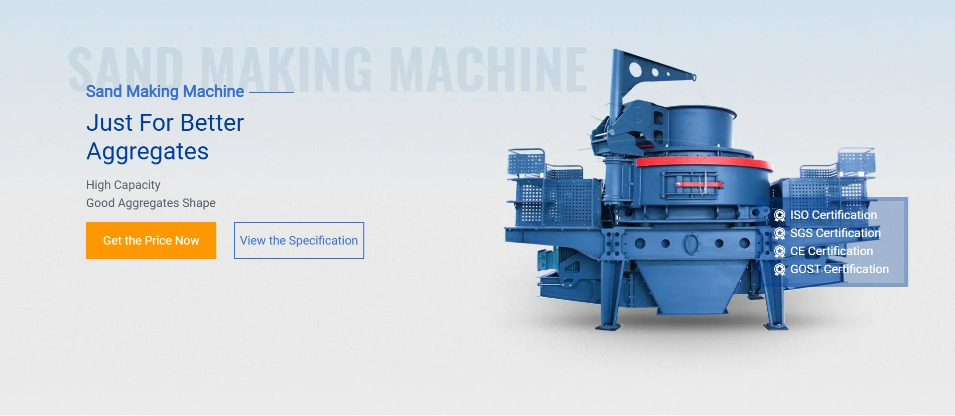
Understanding the schematic diagram of a VSI crusher helps visualize its internal structure and operational mechanics. Below are the primary components:.jpg)
(A) Rotor Assembly
The rotor is the heart of the VSI crusher. It consists of:
– Main Shaft: Connects to the motor via belts or direct drive.
– Impeller Shoes: Replaceable wear parts that accelerate material outward.
– Distributor Plate: Ensures uniform feed distribution into the crushing chamber.
(B) Crushing Chamber
The chamber surrounds the rotor and includes:
– Anvils/Impact Plates: Stationary surfaces where material impacts occur.
– Rock Shelf: Redirects material back into the rotor path for secondary crushing.
– Adjustable Cascade Feed System: Controls material flow for optimal efficiency.
(C) Drive System
VSIs typically employ:
– Electric motor with belt drive or direct coupling.
– Variable frequency drives (VFDs) for speed adjustment.
(D) Feed Hopper & Feed Tube
Material enters through:
– A feed hopper that regulates input size.
– A feed tube directing material centrally into the rotor


