


Table of Contents
- Understanding Sand and Gravel Plant Operations Through Real-World Images
- Key Components of a Sand and Gravel Processing Facility Revealed in Photos
- Exploring Mobile vs. Stationary Plant Setups with Visual Examples
- How Crushing, Screening, and Washing Systems Work: Image-Based Breakdown
- Environmental and Safety Features Seen in Modern Sand and Gravel Plant Photographs
- Frequently Asked Questions
- What are the key components visible in pictures of sand and gravel plants?
- How can you identify a modern sand and gravel processing plant from its photo?
- What types of crushers are most commonly seen in sand and gravel plant pictures?
- How do wet processing vs. dry processing sand and gravel plants differ visually?
- What safety and environmental features can be spotted in professional sand and gravel plant images?
- How do portable sand and gravel plants appear in photographs compared to stationary ones?
- What role does plant layout play in interpreting sand and gravel facility images?
- Where can I find authentic, high-resolution pictures of operational sand and gravel plants?
- What should engineers look for when analyzing sand and gravel plant photos for design validation?
- How do climate adaptations appear in sand and gravel plant photographs?
- Can AI image analysis be used to evaluate sand and gravel plant efficiency from photos?
- What are the differences between quarry-integrated and standalone sand and gravel plants in photos?
Step into the dynamic world of sand and gravel production, where raw earth transforms into essential construction materials through precision engineering and advanced technology. A single glance at a sand and gravel plant reveals a symphony of conveyors, crushers, screens, and washers working in concert to sort, shape, and refine aggregates. These facilities, often sprawling across quarries and riverbeds, are the backbone of modern infrastructure—supplying materials for roads, buildings, and bridges. Photographs of these operations offer more than just visual documentation; they provide insight into the intricate flow of material processing, equipment configuration, and site logistics. From towering crushers reducing boulders to fine gravel, to vibrating screens meticulously separating particle sizes, each image captures the power and precision of industrial-scale processing. This visual guide illuminates the inner workings of sand and gravel plants, showcasing the machinery and layout that define efficiency and productivity in aggregate production.
Understanding Sand and Gravel Plant Operations Through Real-World Images
-
Site Layout and Material Flow
Sand and gravel plant operations are designed around efficient material flow, beginning at the extraction point and ending with stockpiled or loaded finished products. Real-world images reveal a logical progression: raw material delivery via excavators or front-end loaders to primary crushers or scalping screens, often positioned near the quarry face. Conveyor belts dominate the visual landscape, linking processing stages with minimal elevation changes to reduce energy use and maintenance demands. -
Primary Processing Equipment
Photographic evidence consistently highlights jaw crushers and heavy-duty scalping screens as initial processing units. These are frequently mounted on modular or tracked bases, indicating mobility and rapid deployment. In many operations, the first stage removes oversized rock and debris, ensuring only suitably sized material advances. Visual inspection of wear patterns on liners and screen media provides insight into maintenance cycles and feed variability. -
Classification and Washing Systems
Images of log washers, spiral classifiers, and hydrocyclones illustrate the critical role of water in separating sand from silt and clay. These components are typically arranged in series, with water management infrastructure—settling ponds, sumps, and pumps—clearly visible. The turbidity of process water and the condition of settling basins serve as visual indicators of system efficiency and environmental compliance. -
Final Product Handling and Storage
Conveyor terminations feeding radial stackers are a consistent feature, with stockpiles forming distinct cones of segregated aggregates. Aerial or elevated photographs demonstrate spatial planning for product segregation by size and specification. Load-out points adjacent to finished product stockpiles show integration with trucking logistics, often including weighbridges and automated dispatch systems visible in site-wide shots. -
Operational Insights from Visual Data
Repeated visual analysis across multiple sites reveals patterns in equipment alignment, safety zoning, and dust suppression systems. Water spray nozzles at transfer points, belt cleaners, and access platforms are consistently present in operational photos, underscoring adherence to safety and environmental protocols. Unexpected elements—such as ad hoc bypass chutes or modified support structures—often indicate adaptive responses to feed variability or throughput demands.
These real-world images do not merely document equipment; they capture the dynamic interplay of geology, engineering, and operational pragmatism inherent in aggregate processing.
Key Components of a Sand and Gravel Processing Facility Revealed in Photos
-
Primary crusher (jaw or impact): Positioned at the head of the plant, this unit reduces oversized raw material to a manageable size for downstream processing. Typically fed by excavators or loaders, it establishes the initial size reduction necessary for efficient handling.
-
Vibrating grizzly feeder: Installed beneath the crusher feed hopper, this component separates fine material from coarse feed before crushing. It prevents blinding and overloading by bypassing fines directly to the screening circuit, improving throughput and reducing wear.
-
Scalping screen (vibrating): A high-frequency incline screen that removes additional fines and contaminants prior to secondary processing. Efficient scalping ensures only appropriately sized material advances, minimizing load on downstream equipment.
-
Conveyor systems: A network of belt conveyors transports material between processing stages. Designed for durability and alignment precision, they maintain consistent flow rates and minimize spillage through proper skirt sealing and tensioning.
-
Sand screw classifier: Critical for dewatering and cleaning fine aggregates, this unit separates sand from silt and clay via spiral action in a tank of water. The resulting product meets specification for concrete and asphalt applications.
-
Hydrocyclone cluster (in wash plant): Used in high-capacity washing circuits, hydrocyclones separate sand fractions by particle size using centrifugal force. Often paired with dewatering screens for maximum solids recovery.
-
Dewatering screen: A high-frequency vibrating screen that further reduces moisture content in sand and fine aggregates. Coupled with pumps and slurry systems, it produces a stackable, transportable product with less than 15% moisture.
-
Stockpile conveyors and radial stackers: Engineered to distribute processed material into designated storage zones, radial stackers allow controlled pile formation with minimal manual intervention. Boom articulation and slewing capability optimize space utilization.
-
Control house and instrumentation: The operational nerve center, housing PLC systems, motor control centers, and HMI interfaces. Real-time monitoring of motor loads, feed rates, and equipment status ensures safe, efficient plant operation.
-
Dust suppression systems: Comprising water sprays and fog cannons at transfer points, crushers, and screens, these systems mitigate airborne particulates in dry processing environments, ensuring compliance with environmental standards.
Each component functions within an integrated system where material flow, capacity matching, and maintenance access are pre-engineered for peak performance. Proper layout minimizes recirculation, reduces energy consumption, and supports scalability for future expansion.
Exploring Mobile vs. Stationary Plant Setups with Visual Examples
-
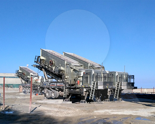
Mobile plants offer rapid deployment and flexibility across multiple sites, making them ideal for short-term contracts, remote locations, or projects requiring frequent relocation. These units integrate crushing, screening, and conveying systems on tracked or wheeled undercarriages, enabling swift setup with minimal site preparation. For example, a mobile jaw crusher paired with a vibrating screen can be operational within hours of arrival, reducing downtime and accelerating project timelines. Visual inspection reveals compact configurations with integrated power packs and hydraulic folding components, minimizing transport footprint.
-
Stationary plants, in contrast, are engineered for permanent or long-term installation at fixed locations with consistent feed supply. They typically deliver higher throughput and greater processing efficiency due to optimized component alignment, larger equipment sizing, and robust structural support. A typical stationary setup includes a primary gyratory crusher feeding multiple stages of secondary and tertiary crushing, supported by large-scale screening and stockpiling conveyors. Footings are concrete-anchored, and infrastructure includes centralized control rooms and dust suppression systems. Visually, these facilities resemble industrial processing hubs with extensive conveyor networks and modular processing zones.
| Feature | Mobile Setup | Stationary Setup |
|---|---|---|
| Deployment Time | Hours to days | Weeks to months |
| Capital Cost | Lower initial investment | Higher capital outlay |
| Flexibility | High – relocatable | Low – fixed infrastructure |
| Throughput Capacity | Moderate (up to ~500 tph) | High (exceeding 1,000 tph) |
| Maintenance Access | Limited by compact design | Full-service access, dedicated maintenance bays |
| Ideal Use Case | Short-term projects, variable feed sources | Long-term aggregate production, large-scale operations |
- The choice between mobile and stationary configurations hinges on project duration, material volume, site logistics, and economic considerations. Mobile units excel in minimizing mobilization costs and adapting to changing terrain, particularly in infrastructure development or demolition recycling. Stationary plants justify their footprint through sustained output, precision grading, and integration with bulk loading and quality control systems. Site-specific visual assessments—such as feed pile placement, discharge routing, and spatial constraints—play a decisive role in optimal plant selection. Ultimately, hybrid approaches combining mobile primary stages with semi-stationary downstream circuits are increasingly adopted to balance agility with processing rigor.
How Crushing, Screening, and Washing Systems Work: Image-Based Breakdown
-
Primary crushing begins with feed material delivered via dump trucks or front-end loaders onto a vibrating grizzly feeder. The feeder separates fines from oversized rock, allowing undersized material to bypass the primary crusher while directing larger rocks into the crushing chamber. Jaw or gyratory crushers reduce boulders to manageable sizes through compressive force between a fixed and oscillating plate.
-
Material discharging from the primary crusher travels along a conveyor to a scalping screen. This vibrating screen removes additional fines and pre-sizes aggregate before secondary processing. Oversized material proceeds to secondary crushing—typically executed by cone or impact crushers—which further reduces particle size to specification.
-
A closed-circuit configuration is often employed: crushed material returns to the screen via a conveyor loop. Particles meeting size criteria report as product; oversize is recirculated for re-crushing. This ensures consistent gradation and maximizes throughput efficiency.
-
Post-crushing, aggregate may undergo tertiary screening for precise classification into final product bins. Multi-deck screens separate material into multiple size fractions—e.g., #57 stone, concrete sand, or drain rock—using progressively finer mesh panels.
-
Sand and fine aggregate streams frequently require washing. Material enters a screw or log washer, where immersion in water and mechanical agitation removes deleterious substances such as clay, silt, and dust. Cleaned sand is dewatered and stockpiled; wastewater flows to a settling tank or high-rate classifier for solids recovery and water reuse.
-
Wash plant effluent is treated in a cyclone and thickener setup, where fine particles are recovered and excess water clarified for recirculation. This closed-loop water management reduces environmental impact and operational costs.
-
Conveyors interconnect all stages, routing material efficiently through elevation changes via incline and radial stackers. Control systems monitor feed rates, screen efficiency, and equipment health to maintain optimal performance.
-
Modular plant designs integrate these components into compact, mobile, or semi-permanent configurations, enabling rapid deployment and scalability based on site requirements and production goals.
-
System performance hinges on correct equipment matching: crusher type, screen aperture, wash capacity, and flow rates must align with feed characteristics and end-product specifications. Proper calibration ensures maximum yield, minimized wear, and consistent product quality.
Environmental and Safety Features Seen in Modern Sand and Gravel Plant Photographs
-
Modern sand and gravel processing plants increasingly integrate engineered environmental and safety features that are readily observable in contemporary facility photographs. These visual cues reflect compliance with regulatory standards, operational best practices, and a commitment to sustainable resource management.
-
Dust suppression systems are one of the most visible environmental controls. Water spray bars mounted at transfer points, feeders, crushers, and screens are commonly seen in operational images, actively mitigating airborne particulate matter. Enclosed conveyor structures with integrated misting systems further reduce fugitive dust emissions, particularly in dry processing environments.
-
Acoustic enclosures and noise-dampening barriers around high-decibel equipment such as crushers and generators appear frequently in plant layouts. These structures, often constructed with composite panels, are strategically placed to reduce sound propagation into surrounding areas, demonstrating adherence to local noise ordinances.
-
Sedimentation ponds and closed-loop water recycling systems are prominent in aerial and site-plan photographs. These features illustrate responsible water management, with recirculation tanks, settling basins, and clarifier units clearly visible. Piping networks returning process water to wash plants underscore efforts to minimize freshwater consumption and prevent discharge of suspended solids.
-
Safety signage, color-coded walkways, and guardrails are systematically installed throughout modern facilities. High-visibility yellow or red railings surround elevated platforms, access ladders, and screening decks. Emergency stop stations and lockout/tagout (LOTO) points are often positioned within clear line of sight along conveyor routes, emphasizing a culture of operational safety.
-
Equipment guarding—such as mesh enclosures around pulleys, drive shafts, and conveyor head/tail pulleys—is consistently present and well-maintained in current imagery. These safeguards prevent inadvertent contact with moving parts and comply with OSHA and MSHA standards.
-
Lighting arrays and surveillance cameras mounted on structural supports or dedicated poles indicate 24/7 operational monitoring and enhanced worker visibility during low-light conditions. Solar-powered lighting is occasionally observed, reflecting incremental adoption of renewable energy sources.
-
Reclamation staging areas and progressive land rehabilitation zones may also be visible at larger operations, particularly in satellite or drone-captured images. Stockpiled topsoil, contour grading, and early-stage vegetation signal forward planning for post-operation site restoration.
Frequently Asked Questions
What are the key components visible in pictures of sand and gravel plants?
High-quality images of sand and gravel plants typically show crushers, screeners, conveyor belts, feeders, washing systems, storage bins, and control panels. Expert-level visuals may also highlight dust collection systems, water recycling units, and modular plant designs, providing insight into material flow and operational efficiency.
How can you identify a modern sand and gravel processing plant from its photo?
Modern sand and gravel plants in photos exhibit modular or portable designs, advanced automation systems, enclosed conveyor structures, environmental safeguards like dust suppression and noise enclosures, and integration with real-time monitoring displays. Expert analysis of such images can reveal compliance with ISO standards and efficient material handling layouts.
What types of crushers are most commonly seen in sand and gravel plant pictures?
Pictures often reveal jaw crushers for primary crushing, followed by cone or impact crushers for secondary and tertiary stages. High-capacity plants may feature vertical shaft impactors (VSI) for producing uniformly shaped sand, identifiable by their compact housing and high-speed rotor design.
How do wet processing vs. dry processing sand and gravel plants differ visually?
Wet processing plants prominently feature dewatering screens, hydrocyclones, sand screws, and settling ponds, while dry processing plants show air separation units, dust collectors, and minimal water piping. Photos of wet plants often include slurry pipelines and water recycling systems, distinguishing them from dry operations.
What safety and environmental features can be spotted in professional sand and gravel plant images?
Expert-reviewed photos may show safety guarding on conveyors, emergency stop stations, signage compliance (OSHA/MSHA), enclosed cabins with air filtration, and noise-reduction barriers. Environmental features include sediment basins, dust suppression nozzles, and solar-powered monitoring stations.
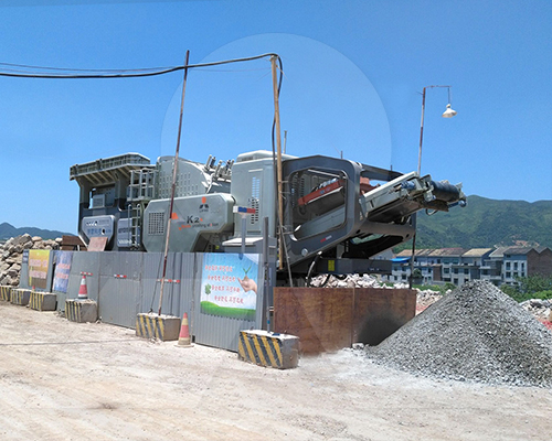
How do portable sand and gravel plants appear in photographs compared to stationary ones?
Portable plants in photos appear on tracked or wheeled chassis with compact configurations, hydraulic folding conveyors, and quick-deployment features. Stationary plants show permanent concrete foundations, larger infrastructure, and extensive conveyor networks extending across fixed sites.
What role does plant layout play in interpreting sand and gravel facility images?
Expert interpretation of layout in photos reveals optimized material flow from quarry feed to product stockpiles, minimizing cross-traffic and energy use. Key indicators include radial stackers, proper screen deck orientation, and crusher placement relative to haul routes.
Where can I find authentic, high-resolution pictures of operational sand and gravel plants?
Authorized images are available through OEM manufacturers (e.g., Metso, Terex, Sandvik), engineering firms, and industry publications like Rock Products or Pit & Quarry. Government mining agency reports and academic case studies also provide verified, high-resolution plant visuals.
What should engineers look for when analyzing sand and gravel plant photos for design validation?
Engineers should assess alignment of equipment for minimal material transfer height, redundancy in screening capacity, adequacy of maintenance access points, and integration of wear-monitoring systems. Expert review of photos can validate design efficiency and predict operational bottlenecks.
How do climate adaptations appear in sand and gravel plant photographs?
Cold-climate plants show enclosed structures, heated enclosures for screens and pumps, and snow-loading considerations on roofs. In arid regions, photos reveal extra dust suppression systems, covered stockpiles, and water conservation infrastructure like closed-loop washing circuits.
Can AI image analysis be used to evaluate sand and gravel plant efficiency from photos?
Yes, using computer vision algorithms, experts can extract equipment dimensions, count operational units, assess conveyor angles, and estimate throughput capacity from aerial or ground-level photos. Machine learning models trained on industrial plant datasets can identify inefficiencies and benchmark against best practices.
What are the differences between quarry-integrated and standalone sand and gravel plants in photos?
Quarry-integrated plants show direct feed from excavators or dump trucks into primary crushers with minimal haul distance, while standalone plants feature larger receiving bins and weighbridge systems for third-party aggregate input. Photos of integrated sites often include drill rigs and blast monitoring equipment nearby.