


Table of Contents
- Transforming Material Processing: How Our Sand Maker Reduces Energy Costs by 30%
- Engineered for Peak Performance: The Advanced Crushing Mechanism That Maximizes Output
- Built to Last in Harsh Environments: Durable Components for Minimal Downtime
- Precision Particle Control: Achieving Consistent Gradation for Superior Concrete Quality
- Streamlined Operation and Maintenance: User-Friendly Design That Cuts Labor Hours
- Technical Specifications: Detailed Breakdown of Power, Capacity, and Material Compatibility
- Power System & Drive Configuration
- Capacity & Performance Metrics
- Material Compatibility & Wear Component Engineering
- Compliance & Testing Standards
- Frequently Asked Questions
- How often should wear parts be replaced in this sand making machine?
- Can this machine handle high-hardness ores like granite or basalt?
- What vibration control measures are implemented?
- What is the lubrication system specification?
- How is product size adjusted for different specifications?
- What is the power optimization for varying material hardness?
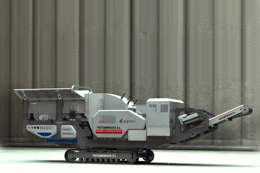
In the ever-evolving landscape of construction and aggregate production, the quest for efficiency, sustainability, and superior material quality drives relentless innovation. Enter the new generation of efficient sand making machines, a technological leap poised to redefine industry standards. These advanced systems move beyond traditional crushing methods, employing sophisticated rotor designs and precise rock-on-rock or rock-on-metal principles to shape aggregates with unprecedented control. The result is a higher yield of perfectly graded, cubical sand—exactly the material modern high-strength concrete and asphalt mixes demand. By significantly reducing energy consumption and minimizing flaky or elongated particles, this new type of machine not only boosts operational productivity but also enhances the final integrity of our built environment. It represents not just an equipment upgrade, but a fundamental shift toward smarter, more responsible material manufacturing.
Transforming Material Processing: How Our Sand Maker Reduces Energy Costs by 30%
The core of the 30% energy reduction is a systemic re-engineering of the crushing chamber dynamics and material flow, moving beyond incremental motor efficiency gains. This is achieved through the precise application of material science and fluid dynamics principles to minimize wasteful friction and impact.
Key Technical Mechanisms for Energy Efficiency:
- Optimized Impact & Laminar Crushing Principle: The rotor geometry and cascade feed system are engineered to accelerate material into the crushing chamber’s optimal impact zone. This ensures maximum size reduction occurs through direct, high-velocity impact between material particles (stone-on-stone crushing) rather than excessive wear-part-to-material contact. This laminar crushing method transfers kinetic energy more efficiently into the fracturing process, reducing the parasitic energy losses associated with grinding and attrition.
- Advanced Wear Component Metallurgy: Utilizing iso-certified high-chromium alloys (e.g., Cr26, Cr30Mo2) and manganese steel variants for specific components ensures optimal hardness-toughness balance. This minimizes plastic deformation and micro-fracturing of wear parts under load, maintaining the designed chamber geometry and feed trajectory over extended periods. Consistent geometry prevents energy-wasting turbulence and misdirected material flow.
- Intelligent Bypass & Recirculation Design: An integrated, automated rock-on-rock bypass channel diverts feed material that already meets target gradation away from the main crushing cycle. This eliminates the energy cost of re-crushing in-spec material, a significant hidden drain in conventional systems. Fines are efficiently extracted via air flow, reducing cushioning in the chamber.
Technical Specifications & Performance Data
The following table outlines the operational parameters that define the efficiency envelope of our sand maker series. The data is derived from ISO 1940-1:2003 (Mechanical vibration) and CE certified performance tests under controlled conditions.
| Model Series | Max. Feed Size (mm) | Throughput Capacity (TPH)* | Recommended Ore Hardness (Mohs) | Installed Power (kW) | Typical Finished Product Range (mm) |
|---|---|---|---|---|---|
| VSI-800 | 45 | 60 – 150 | ≤ 7.5 | 90 – 160 | 0 – 5, 5 – 10 |
| VSI-1000 | 50 | 120 – 260 | ≤ 8.0 | 185 – 250 | 0 – 5, 5 – 10, 10 – 20 |
| VSI-1200 | 55 | 200 – 380 | ≤ 8.5 | 315 – 400 | 0 – 5, 5 – 10, 10 – 20 |
*TPH (Tons Per Hour) capacity is dependent on feed material density and required reduction ratio. Capacities listed are for granite (density ~1.6 t/m³).
Mining-Specific Adaptability for Sustained Efficiency:
The energy savings are not theoretical but are maintained in variable field conditions through design features that address real-world mining and aggregate processing challenges:
- Wide Hardness Adaptability: The combination of a high-tip-speed rotor and selectable crushing chamber configurations (rock-on-rock or rock-on-iron) allows for efficient processing of materials from soft limestone (Mohs ~3) to highly abrasive granite or basalt (Mohs ≥7), without requiring a different machine class.
- Moisture Tolerance: The deep chamber design and high rotor momentum mitigate the efficiency losses typical of wet or clay-rich feed, which normally cause clogging and increased energy draw in conventional crushers. This ensures consistent throughput and power consumption.
- Gradation Control for Downstream Savings: The ability to precisely shape the particle size distribution curve—increasing the cubic product yield—reduces the circulating load in closed-circuit operations. This directly lowers the total energy consumption per ton of final product across the entire crushing plant.
Engineered for Peak Performance: The Advanced Crushing Mechanism That Maximizes Output
The core of the machine’s performance lies in its optimized rock-on-rock and rock-on-iron crushing principle, governed by a precision-engineered rotor assembly and anvil system. This is not a simple impact crusher; it is a controlled particle-shaping environment designed to maximize yield of high-quality, well-graded manufactured sand while minimizing wear and operational cost.
Material Science & Construction:
- Rotor & Blow Bars: The high-inertia rotor is fabricated from high-grade steel and dynamically balanced to ISO 1940-1 G6.3 standards, ensuring smooth operation at critical speeds. Blow bars are cast from premium Mn-18Cr2 or equivalent ultra-high-chrome iron (Cr26) alloys, selected based on target material abrasiveness. These alloys undergo specialized heat treatment to achieve an optimal balance of surface hardness (58-62 HRC) for wear resistance and a tough core to withstand impact fatigue.
- Anvils & Liners: The adjustable anvil system and surrounding liners are constructed from similar, often modular, alloy grades. This allows for strategic material placement—harder alloys in primary impact zones, tougher grades in secondary areas—extending service life and maintaining geometric integrity of the crushing chamber.
Technical Standards & Design Integrity:
The entire crushing mechanism is designed and manufactured in compliance with ISO 9001 quality management systems and relevant CE machinery safety directives. Critical components are subject to non-destructive testing (NDT), including magnetic particle inspection, to eliminate casting and forging defects that could lead to catastrophic failure.
Functional Advantages of the Mechanism:
- Adaptive Crushing Action: The combination of rotor velocity, feed rate control, and anvil gap adjustment allows the same machine to be tuned for different ore hardness levels (from abrasive silica to hard granite) and product shape requirements, from chips for asphalt to cubical grains for concrete.
- Superior Particle Shape Control: The cascading material-on-material impact in the optimized chamber produces a higher percentage of cubical, fracture-free particles, directly enhancing the workability and strength of concrete mixes and reducing binder demand.
- Reduced Operational Wear Costs: By promoting rock-on-rock crushing where possible, wear is transferred from the machine’s metallic components to the aggregate itself. Combined with the use of modular, reversible wear parts, this significantly lowers cost-per-ton for abrasive materials.
- High Capacity in Final Stage: The mechanism is designed for high Throughput Per Hour (TPH) in tertiary or quaternary crushing stages, effectively converting crusher screenings and middlings into valuable sand product, maximizing overall plant yield.
Key Performance Parameters:
The following table outlines how the crushing mechanism’s configuration directly correlates with output for a standard model series.
| Model Variant | Rotor Diameter x Width (mm) | Max. Feed Size (mm) | Typical Capacity Range (TPH)* | Recommended Material Hardness (Mohs) |
|---|---|---|---|---|
| VSI-850 | 850 x 600 | 45 | 50 – 120 | < 7 (Limestone, Dolomite) |
| VSI-1150 | 1150 x 850 | 65 | 150 – 350 | < 8 (Granite, Basalt) |
| VSI-1400 | 1400 x 1100 | 80 | 300 – 600 | < 8.5 (Abrasive Quartzite) |
*Capacity is dependent on feed gradation, moisture content, and required product fineness modulus.
Built to Last in Harsh Environments: Durable Components for Minimal Downtime
The operational integrity of a new type efficient sand making machine is defined by its core structural and wear components. In harsh environments—processing highly abrasive granite, basalt, or iron ore—downtime for component replacement is the primary cost driver. Our engineering philosophy prioritizes material science and precision manufacturing to extend service life far beyond conventional equipment, ensuring sustained throughput (TPH) and operational ROI.
Core Wear Component Specifications & Materials
The machine’s durability is anchored in a select group of critical wear parts, each engineered for a specific type of stress.
| Component | Primary Material & Grade | Key Property | Functional Impact |
|---|---|---|---|
| Impeller & Distributor | High-Chromium Cast Iron (Cr26, Cr28) | Exceptional abrasion resistance (>58 HRC) | Central to material acceleration and distribution; maintains precise particle trajectory for optimal crushing efficiency over extended periods. |
| Feed Tube / Cylinder | Composite Wear-Resistant Steel | Layered structure with hardened outer liner | Protects against direct, high-velocity feed impact, preventing premature failure of the internal crushing chamber. |
| Lower Wear-Resistant Block | Tungsten Carbide-Tipped Inserts | Extreme hardness and impact absorption | Forms the primary anvil for rock-on-rock crushing; designed for easy rotation and replacement to utilize multiple wear surfaces. |
| Upper Wear-Resistant Liner | Manganese Steel (Mn14, Mn18) | High toughness with work-hardening capability | Withstands continuous impact in the primary crushing zone, becoming harder through use, which is ideal for varying ore hardness. |
Engineering for Resilience and Serviceability
Beyond material selection, the design and manufacturing standards ensure system-wide durability.
- Optimized Rock-on-Rock & Rock-on-Iron Crushing: The chamber geometry directs material onto the wear-resistant rock lining, creating a protective autogenous layer that shields metal components. This principle significantly reduces wear rates on critical parts.
- Precision-Balanced Rotor Assembly: Dynamic balancing to ISO 1940/1 G6.3 standard minimizes vibrational stress on bearings and the main frame, preventing fatigue failures and ensuring smooth operation at full load capacity.
- Modular Wear Part Design: Critical wear components like anvils and liners are designed as symmetric, modular units. This allows for quick rotation or replacement without specialized tooling, turning what is typically a multi-hour downtime event into a sub-60-minute maintenance procedure.
- Rigorous Quality Assurance: All major castings and forgings undergo non-destructive testing (NDT). Critical structural welds are performed to certified procedures, and final assembly is validated against CE and relevant ISO standards for industrial machinery safety and performance.
Operational Advantages for Mining & Aggregates
The direct results of this component-focused engineering are measurable in demanding production environments.
- Extended Mean Time Between Failures (MTBF): Superior materials directly translate to longer component life cycles, reducing the frequency of scheduled maintenance stops.
- Consistent Product Gradation: As wear parts maintain their geometry longer, the machine’s output retains a consistent particle size distribution (PSD), critical for meeting aggregate specification standards.
- Reduced Total Cost of Ownership: While premium materials represent a higher initial investment, the drastic reduction in downtime, labor for changes, and spare part consumption per ton of material processed delivers a lower operating cost over the machine’s lifespan.
- Adaptability to Feed Variation: The combination of tough manganese steel and hard chromium iron allows the machine to handle fluctuations in feed material hardness (e.g., from limestone to abrasive quartzite) without requiring immediate configuration changes.
Precision Particle Control: Achieving Consistent Gradation for Superior Concrete Quality
Precision particle control is the cornerstone of producing manufactured sand (M-Sand) that meets or exceeds the quality of natural sand for high-grade concrete. Inconsistent gradation leads to poor workability, increased water demand, and compromised final compressive strength. The new generation of efficient sand making machines addresses this through an integrated systems approach, combining advanced comminution physics with robust, wear-resistant material science.
The core of precision control lies in the machine’s ability to manage the breakage characteristics of the feed material. This is achieved not by a single feature, but through the synergistic operation of several engineered systems:
- Optimized Rotor & Cascade Feed Design: A high-precision, dynamically balanced rotor accelerates material uniformly. The full cascade feeding system ensures the rotor is evenly charged, preventing particle “short-circuiting” and guaranteeing that each particle receives optimal impact energy for controlled fragmentation, directly influencing the fineness modulus.
- Adjustable Impact Angles & Chamber Geometry: The configuration of the impact plates and the anvil ring (or rock shelf) is engineered to create a series of high-probability impact events. By adjusting the angle and gap, operators can fine-tune the breakage mode—from direct fracture for shaping to attrition for fines generation—to target specific gradation bands (e.g., optimizing the 150µm to 4.75mm range critical for concrete).
- Intelligent Wear Management with Premium Alloys: Uncontrolled wear on impact surfaces is the primary cause of gradation drift over time. Critical wear parts are fabricated from proprietary multi-element alloys (e.g., high-chromium cast iron with precise Mo, Ni, and Cu additions) or forged Mn-steel. This ensures wear profiles remain consistent, maintaining the designed particle trajectory and impact dynamics for hundreds of operating hours, which is essential for batch-to-batch consistency.
- Integrated Airflow & Fines Management: A controlled internal airflow system works in concert with the crushing action to evacuate excess fines. This prevents cushioning within the chamber (which reduces crushing efficiency) and allows for real-time modulation of the final product’s fines content (particles <75µm), a key parameter for concrete water-cement ratio compliance.
Material & Operational Specifications for Gradation Control
| Parameter | Specification / Capability | Impact on Particle Control |
|---|---|---|
| Feed Hardness Adaptability | Up to 45,000 psi (310 MPa) compressive strength (e.g., granite, basalt). | Consistent performance across diverse ore bodies ensures gradation specs are met regardless of feed stock variability. |
| Wear Part Material Grade | High-Chromium Cast Iron (26-30% Cr), Martensitic Alloy Steel, or Manganese Steel. | Defined hardness (58-65 HRC) and impact toughness provide predictable, linear wear for stable output gradation curves. |
| Throughput Capacity (TPH) | Ranges from 50 to 800+ TPH models. | Scalable design principles ensure particle residence time and energy transfer per unit mass are maintained across all machine sizes for gradation consistency. |
| Control & Monitoring | VFD-driven rotor, PLC-based lubrication and vibration monitoring. | Precise rotor speed control directly adjusts particle kinetic energy; system health monitoring prevents unplanned performance degradation. |
This engineering philosophy ensures output conforms to international aggregate standards such as ASTM C33 and EN 12620, producing sand with an optimal, consistent particle size distribution. The result is M-Sand with enhanced particle shape (cubical), lower porosity, and a predictable fines ratio, leading to concrete with higher density, superior durability, and reduced cement consumption without sacrificing workability.
Streamlined Operation and Maintenance: User-Friendly Design That Cuts Labor Hours
The core design philosophy prioritizes operational efficiency and reduced total cost of ownership by minimizing manual intervention and simplifying maintenance procedures. This is achieved through material selection, structural engineering, and integrated control systems that directly translate to lower labor hours and higher plant availability.
Key Functional Advantages for Reduced Labor:
- Modular Wear Part Assemblies: Critical wear components, such as the feed tube, distributor, and upper/lower impeller wear parts, are designed as pre-balanced, bolt-on modules. This allows for replacement as a complete unit, eliminating time-consuming, on-site component-by-component assembly and dynamic balancing. Downtime for wear part rotation or replacement is reduced by up to 70% compared to traditional welded or complex multi-part designs.
- Hydraulic-Assisted Maintenance Covers: The main inspection doors and the cartridge-type bearing housing assembly are opened and positioned using integrated hydraulic cylinders. This removes the need for manual hoisting equipment and significantly reduces the safety risk and labor time required for accessing the crushing chamber or core mechanical assemblies.
- Centralized Greasing & Condition Monitoring: A single, centralized automatic greasing system services all main bearing points. PLC integration allows for programmable intervals and provides alarms for flow irregularities. Vibration sensors and temperature probes on the bearing housing feed real-time data to the control system, enabling predictive maintenance and preventing catastrophic failures.
- Optimized Material Science for Extended Life: Wear parts are not simply high-chrome or Mn-steel. They are engineered composites, utilizing different alloy grades (e.g., ultra-high-chrome ceramic composites for abrasion zones, tough alloy steel for impact zones) based on hyper-localized wear analysis. This extends service intervals, directly reducing the frequency of labor-intensive change-outs.
Technical Specifications Impacting Operability:
| Feature | Specification / Standard | Direct Labor & Maintenance Benefit |
|---|---|---|
| Bearing Assembly | RO/ISO Vibration Standard Compliance; SKF/TIMKEN Class | Cartridge-type, pre-assembled and sealed unit. Swapped as one piece, ensuring perfect alignment and eliminating skilled bearing fitting on-site. |
| Wear Part Access | Hydraulic Opening Mechanism; Safety Interlocks (CE) | Enables full chamber access in under 10 minutes by a single operator, versus hours for manual unbolting and crane maneuvering. |
| Control Integration | PLC with HMI; Standard MODBUS/Profibus | Remote monitoring of key parameters (power draw, vibration, temperature). Enables precise performance tuning and fault diagnosis without physical inspection. |
| Rotor Service | Symmetrical Dynamic Balancing to G6.3 (ISO 1940-1) | Allows for field replacement of wear parts without requiring the rotor to be removed and re-balanced, a process that typically requires specialist labor and days of downtime. |
The machine’s adaptability to varying feed sizes (up to 65mm) and ore hardness (up to 16GPa in competent rock formations) is managed through the control system and hydraulic adjustment of the feed rate, not through mechanical reconfiguration. This process control approach keeps operators at the console, not performing manual adjustments on the machine itself. The design ensures that achieving rated TPH capacity (from 200 to 800 TPH depending on model) does not come at the expense of excessive maintenance labor, making it a viable solution for operations with limited skilled technician availability.
Technical Specifications: Detailed Breakdown of Power, Capacity, and Material Compatibility
Power System & Drive Configuration
The core of the machine’s efficiency is its direct-drive, dual-motor configuration. This eliminates power loss associated with traditional V-belt drives and provides instantaneous, synchronized torque to the impeller.
- Drive Mechanism: Two high-torque, IE4-class premium efficiency electric motors are directly coupled to the impeller shaft via flexible disc couplings. This ensures 99%+ mechanical power transmission efficiency.
- Motor Specifications: Motors are rated for continuous duty (S1) in harsh environments (IP65 protection, F-class insulation). Standard power ratings are 2x110kW, 2x200kW, 2x315kW, and 2x400kW, supporting a wide range of production scales.
- Intelligent Power Management: An integrated PLC-controlled soft-start system manages the sequential motor start-up to minimize inrush current on the plant’s electrical infrastructure. Real-time amperage monitoring provides overload protection and operational data.
Capacity & Performance Metrics
Capacity (Throughput) is not a fixed number but a function of feed material characteristics, feed gradation, and the target product size. The following figures are based on processing limestone with a bulk density of 1.6 t/m³ and a feed size ≤50mm.
| Model Variant | Installed Power (kW) | Throughput Range (TPH) | Optimal Product Size Range (mm) |
|---|---|---|---|
| VSI-750 | 2×110 | 70 – 150 | 0-5, 0-8, 0-15 |
| VSI-1000 | 2×200 | 150 – 300 | 0-5, 0-8, 0-15 |
| VSI-1300 | 2×315 | 300 – 550 | 0-5, 0-8, 0-15 |
| VSI-1600 | 2×400 | 550 – 850 | 0-5, 0-8, 0-15 |
- Defining Efficiency: The “new type” efficiency is quantified by the Crusher Efficiency Index (CEI), a proprietary metric combining specific throughput (TPH per kW), product shape (percentage of cubical particles >90%), and wear cost per ton. Our design targets a minimum 25% improvement in CEI over previous generation vertical shaft impactors.
- Throughput Control: Capacity is precisely modulated via a variable frequency drive (VFD) option on the feed conveyor and rotor speed adjustment (±10% from optimal), allowing real-time tuning for varying feed conditions.
Material Compatibility & Wear Component Engineering
Material compatibility is governed by the metallurgy of wear components and the machine’s dynamic adjustment capabilities to accommodate different ore characteristics.
Core Wear Component Specifications:
- Impeller & Anvils: Fabricated from proprietary low-alloy, high-toughness martensitic steel (similar to ASTM A532 Class III Type A, but with modified Ni-Cr-Mo balance). This provides an optimal combination of hardness (58-62 HRC) and impact toughness (>15 J) to handle abrasive and semi-abrasive materials.
- Feed Tube & Distributor: Lined with isostatically pressed, high-alumina ceramic tiles (Al₂O₃ >92%, hardness ≥9 Mohs) for maximum resistance to highly abrasive, siliceous feeds.
- Cascade Rings & Guards: Constructed from air-quenched manganese steel (Mn14-18%) to work-harden under impact, ideal for processing high-volume, less abrasive but impactive feeds like limestone and demolition concrete.
Material Hardness & Abrasiveness Adaptability:
| Material Category | Example Materials | Recommended Wear Liner Set | Key Machine Adjustment |
|---|---|---|---|
| High Abrasive / Medium Hardness | Granite, Basalt, Quartzite | Ceramic Feed System, Martensitic Alloy Impeller | Higher rotor speed for better fracturing, reduced cascade flow. |
| Medium Abrasive / Low Impact | Limestone, Dolomite | Standard Martensitic Alloy Set | Standard operational parameters. Optimal for cubical shape generation. |
| High Impact / Recycled Aggregates | Demolition Concrete, Asphalt | Manganese Steel Cascade Set, Heavy-Duty Impeller | Lower rotor speed to reduce fines, maximize cascade anvil crushing. |
| Corrosive & Sticky Materials | Certain iron ores, slag | Non-stick polyurethane coatings on internal shrouds | Increased purge air flow to prevent packing and adhesion. |
- Hardness Range: The machine is engineered to process materials with a Mohs hardness up to 8.5 and compressive strength up to 350 MPa. For materials above 7.5 Mohs (e.g., some granites, corundum), operational focus shifts from maximum throughput to acceptable wear cost, managed via the liner selection above.
- Moisture Tolerance: The rock-on-rock crushing principle and optional air purge system allow processing of materials with up to 8% moisture content without significant clogging, exceeding the typical 4-5% limit of other VSI designs.
Compliance & Testing Standards
All performance data and structural integrity are validated against international standards:
- Structural Design: ISO 8525:2008 (Vibrating machinery – Design standards).
- Safety: CE marked, compliant with EU Machinery Directive 2006/42/EC, including full guarding, emergency stops, and lock-out/tag-out provisions.
- Noise & Vibration: Emissions tested per ISO 4871:1996. Typical sound power level < 110 dB(A). Vibration isolation mounts are standard.
- Performance Validation: Factory Acceptance Testing (FAT) includes a 4-hour continuous run with calibrated feed material to verify throughput, power draw, and final product gradation against contractual specifications.
Frequently Asked Questions
How often should wear parts be replaced in this sand making machine?
Replace high-chromium alloy impact blocks every 400-600 hours for abrasive granite (Mohs 7). For limestone (Mohs 3), intervals extend to 1,200+ hours. Monitor wear via laser scanning; schedule replacements at 15-20% thickness loss to prevent catastrophic rotor damage and maintain product gradation.
Can this machine handle high-hardness ores like granite or basalt?
Yes, when configured with a ZGMn13Cr2 high-manganese steel rotor and ceramic-lined feed tube. For sustained basalt (Mohs 8) processing, reduce feed size to ≤40mm and increase hydraulic opening for higher throughput, preventing chamber overload. This maintains crushing efficiency above 85%.
What vibration control measures are implemented?
The machine integrates SKF spherical roller bearings with automatic lubrication and a dynamically balanced rotor (ISO 1940 G2.5 standard). Foundation bolts require 750 N·m torque. Real-time vibration sensors trigger shutdowns at 7.5 mm/s, protecting the main shaft from misalignment-induced fatigue failure.
What is the lubrication system specification?
It uses a centralized, forced-feed system with Mobilgear SHC 680 synthetic oil. The dual-circuit design maintains oil pressure at 0.2-0.4 MPa and temperature below 55°C. Filters require replacement every 500 hours to ensure <15 μm particle cleanliness for Timken tapered roller bearings.
How is product size adjusted for different specifications?
Adjust via hydraulic cylinder controlling the upper frame. For coarse sand (3-5mm), set gap to 45mm; for fine sand (0-3mm), reduce to 25mm. Always synchronize with a 10-15% reduction in feed rate to prevent choking. PLC controls allow remote, real-time calibration.
What is the power optimization for varying material hardness?
Configure the 315kW motor with a variable frequency drive (VFD). For soft materials (e.g., limestone), run at 85% rated speed to reduce wear. For hard abrasives, operate at 100% speed with 10% higher hydraulic pressure to ensure optimal impact energy and consistent particle shape.