


Table of Contents
- Understanding Mobile Crusher Screen CAD Drawings for Efficient Design
- Key Components of a Mobile Crusher Screen in CAD Modeling
- How to Access and Customize Standard CAD Drawings for Mobile Crushers
- Optimizing Screen Design with CAD: Vibration, Flow, and Structural Integrity
- Applications and Industry Standards for Mobile Crusher Screen CAD Files
- Frequently Asked Questions
- What is a CAD drawing for a mobile crusher screen used for?
- Can I get a DWG file of a mobile crusher screen from equipment manufacturers?
- How do I modify a CAD model for a mobile crusher screen to fit custom applications?
- What standards govern the design of mobile crusher screen CAD drawings?
- How accurate are third-party CAD models of mobile crusher screens?
- What file formats are best for sharing mobile crusher screen CAD drawings?
- How do I integrate a mobile crusher screen CAD model into a plant layout design?
- Are there CAD libraries specifically for mining and aggregate equipment?
- What key dimensions must be included in a mobile crusher screen CAD drawing?
- How can I verify the structural integrity of a custom mobile crusher screen design using CAD?
- Can CAD drawings of mobile crusher screens include hydraulic and electrical schematics?
- What is the role of BIM in mobile crusher screen deployment?
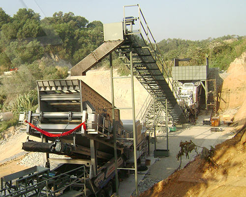
In the fast-evolving world of aggregate processing and mining operations, precision engineering begins long before equipment hits the field—with the CAD drawing at the heart of innovation. The mobile crusher screen, a cornerstone of efficient material separation, relies heavily on meticulously crafted digital designs to ensure optimal performance, durability, and adaptability across diverse job sites. Utilizing advanced Computer-Aided Design (CAD) technology, engineers can model every intricate component—from vibrating mechanisms and screen decks to hydraulic systems and structural frameworks—with unparalleled accuracy. These digital blueprints not only streamline manufacturing and assembly but also enable rapid prototyping, clash detection, and performance simulation under real-world conditions. As demand for compact, high-capacity, and transportable crushing solutions grows, so does the importance of intelligent design optimization within the CAD environment. This article explores the critical components of CAD drawings for mobile crusher screens, highlights best practices in design methodology, and delivers actionable insights to enhance efficiency, reduce downtime, and maximize return on investment in today’s competitive materials processing landscape.
Understanding Mobile Crusher Screen CAD Drawings for Efficient Design
-
Interpretation of mobile crusher screen CAD drawings begins with a precise understanding of coordinate systems and scale conventions. Standardized units—typically millimeters or inches—must be verified to ensure dimensional accuracy across assemblies.
-
Orthographic projections, including top, front, and side views, provide the foundational spatial context. Isometric views supplement these by illustrating three-dimensional relationships among components such as the vibrating screen box, feed chute, drive mechanism, and support structure.
-
Layer organization within CAD files follows industry-standard naming: structural (frames, beams), mechanical (bearings, exciters), electrical (cabling, control panels), and hydraulic/pneumatic systems. Each layer must be independently reviewable to assess integration and clearance.
-
Critical dimensions are annotated with geometric dimensioning and tolerancing (GD&T) symbols to specify form, orientation, and location. Tolerance stack-up analysis is essential to prevent misalignment during on-site assembly.
-
Component callouts reference a bill of materials (BOM) embedded within or adjacent to the drawing. The BOM must detail part numbers, material specifications, weights, and supplier information to facilitate procurement and maintenance.
-
Flow dynamics are implied through inlet and outlet positioning, sloped surfaces, and screen deck angles. Optimal screening efficiency requires verification of material trajectory and residence time via simulation-backed CAD modeling.
-
Mobility features—folding conveyor arms, retractable outriggers, and axle positioning—are depicted in deployed and transport configurations. Kinematic studies embedded in the CAD model ensure full range of motion without interference.
-
Standardized symbols per ISO 128 and ASME Y14.5 govern line types: continuous for visible edges, dashed for hidden features, and phantom lines for alternate positions. Centerlines define symmetry and mounting axes.
-
Revision blocks track design iterations with timestamps, responsible engineers, and change descriptions. Controlled revision management prevents field errors during manufacturing or retrofitting.
-
Design for manufacturability (DFM) and design for assembly (DFA) principles are validated through interference checks, weld accessibility analysis, and lifting point assessments—all derived from the CAD model.
-
Digital integration with finite element analysis (FEA) and computational fluid dynamics (CFD) allows real-time validation of structural integrity and material flow under operational loads.
-
Final output formats (e.g., .DWG, .STEP, .PDF) must preserve metadata and layer integrity for cross-platform collaboration between OEMs, fabricators, and end users.
Key Components of a Mobile Crusher Screen in CAD Modeling
-
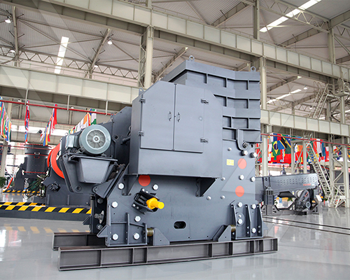
Frame Assembly
The structural backbone of a mobile crusher screen, the frame assembly provides rigidity and load distribution. In CAD modeling, precise alignment of cross-members, side plates, and mounting points is essential to ensure stress resistance during transport and operation. Finite element analysis (FEA)-ready geometry with accurate material assignments allows for early validation of structural integrity under dynamic loads. -
Crusher Unit Integration
Modeled with exact spatial relationships to auxiliary systems, the crusher unit must accommodate feed chute geometry, eccentric shaft positioning, and toggle mechanism kinematics. Parametric modeling enables quick iteration for different crusher types (e.g., jaw, cone, impact). Clearance zones for maintenance access and wear part replacement must be explicitly defined in 3D space. -
Vibrating Screen Deck
The screen deck is modeled with precise incline angles, deck layers, and vibration amplitude envelopes. CAD representations include tensioning mechanisms for screen media, support rails, and isolation springs. Dynamic motion simulation within the CAD environment verifies stroke patterns and ensures no interference during oscillation. -
Conveyor Systems
Integrated folding conveyors require kinematic constraints and pivot points to be accurately defined. Path analysis ensures clearance during deployment and retraction. Drive pulley, idler rolls, and belt tracking mechanisms are modeled with proper tolerances to support downstream manufacturing and assembly. -
Hydraulic and Power Pack Modules
These subsystems are positioned considering serviceability and fluid routing. In CAD, hose bend radii, cylinder stroke limits, and pump mounting orientations are validated. Routing paths for hydraulic lines are modeled to avoid pinch points and excessive flexing. -
Mobility and Chassis Components
Axles, tires, suspension systems, and towing hitches are designed with real-world ground clearance and articulation angles. CAD models incorporate turning radius simulations and weight distribution calculations to ensure transport compliance. -
Ancillary Supports
Ladders, walkways, guardrails, and equipment platforms are modeled to meet safety standards (e.g., OSHA, ISO). Structural connections are detailed with weld symbols and fastener specifications directly embedded in the drawing set.
Each component is developed using parametric constraints and assembly-level design intent to allow scalable adaptation across mobile crushing configurations. Interference checks, mass property analysis, and design for manufacturability (DFM) are systematically applied throughout the modeling process to minimize rework and ensure seamless integration across mechanical subsystems.
How to Access and Customize Standard CAD Drawings for Mobile Crushers
-
Access standard CAD drawings for mobile crushers through authorized manufacturer portals, engineering databases, or licensed design platforms. Ensure proper credentials and compliance with intellectual property rights when retrieving files. Most OEMs provide downloadable CAD models in multiple formats—such as STEP, IGES, DWG, and SLDPRT—for compatibility with major CAD software including AutoCAD, SolidWorks, and Autodesk Inventor.
-
Verify file integrity and version control prior to integration into design workflows. Use metadata and revision notes to confirm alignment with current technical specifications and safety standards. Cross-reference drawing numbers with equipment serials or model designations to avoid mismatches in component dimensions or mounting configurations.
-
Customize drawings using parametric modeling techniques to adapt structural elements, conveyor layouts, or screening decks to site-specific requirements. Focus modifications on feed height, discharge configuration, and chassis dimensions while maintaining load path integrity and dynamic stability. Retain key mounting interfaces and hydraulic/pneumatic connection points to ensure serviceability and component interchangeability.
-
Employ modular design principles when altering screening modules or crusher housings. This enables rapid reconfiguration between single- and double-deck screens or different crusher types (e.g., jaw vs. impact). Ensure all modifications comply with FEA-validated stress limits and dynamic load assumptions under operational conditions such as vibration, impact loading, and material surges.
-
Validate customized models through digital simulation, including kinematic analysis for screen motion and interference checks across moving components. Conduct clearance reviews for maintenance access, especially around tensioning mechanisms, drive assemblies, and quick-change screen media systems.
-
Embed metadata, tolerance callouts, and surface finish specifications directly into the drawing to support manufacturing and quality control. Include weld symbols, fastener specifications, and alignment benchmarks to reduce fabrication errors.
-
Share revised drawings via secure collaboration platforms that support version tracking and stakeholder markup. Require engineering sign-off before releasing designs for prototyping or production. Maintain an auditable revision trail for compliance with ISO 12100 (machinery safety) and regional equipment directives.
-
Archive both native and neutral-format files with descriptive naming conventions for future retrieval and retrofitting. Integrate updated models into asset lifecycle management systems to streamline spare parts provisioning and field upgrades.
Optimizing Screen Design with CAD: Vibration, Flow, and Structural Integrity
-
Optimize vibration dynamics by modeling excitation forces and natural frequencies within CAD to avoid resonance conditions that compromise screening efficiency and component longevity.
-
Utilize modal analysis tools integrated with CAD platforms to identify critical vibration modes of screen panels, support beams, and side plates under operational loads.
-
Simulate dynamic deflection under variable feed rates and particle sizes to ensure consistent stroke amplitude and trajectory across the screen surface.
-
Incorporate motion trajectory studies using time-step simulations to validate elliptical or linear motion profiles, ensuring effective stratification and particle discharge.
-
Model material flow through the screen box using particle dynamics overlays in CAD, aligning aperture layout and deck inclination with bulk material characteristics such as moisture content, size distribution, and flowability.
-
Optimize deck configuration by simulating layer velocity gradients to minimize blinding and pegging, enhancing throughput and screening accuracy.
-
Position feed inlet geometry to promote even material distribution across the full width, reducing edge loading and wear concentration.
-
Evaluate multiple aperture patterns virtually—square, round, slot—based on cut-point requirements and conduct open-area analysis to maximize effective screening surface.
-
Perform structural integrity assessments using finite element analysis (FEA) within the CAD environment to validate stress distribution in high-load zones, particularly at beam junctions and vibrator mounting points.
-
Apply real-world load cases, including startup surge, unbalanced vibration forces, and impact loads from oversized material, to verify factor of safety margins.
-
Optimize frame topology through iterative lightweighting—reducing mass without sacrificing rigidity—by reinforcing stress-concentrated regions with gussets or ribbing modeled directly in CAD.
-
Ensure weldment feasibility by designing accessible joints and avoiding geometric interferences that compromise fabrication quality.
-
Integrate serviceability considerations: design modular panels and quick-release fasteners within the assembly model to reduce downtime during maintenance.
-
Validate clearance envelopes for screen media replacement and vibrator access under confined mobile site conditions.
-
Coordinate component interfaces—bearings, springs, drive couplings—with tolerance stack-up analysis to prevent misalignment-induced failures.
CAD-driven optimization enables a holistic balance between vibrational performance, material flow efficiency, and structural resilience. By embedding simulation early in the design cycle, engineers mitigate field failure risks, enhance screening efficiency, and extend service life—critical for mobile crusher screens subjected to variable and demanding operating conditions.
Applications and Industry Standards for Mobile Crusher Screen CAD Files
-
Mobile crusher screen CAD files are integral to modern aggregate, mining, and recycling operations, enabling precise design, rapid deployment, and seamless integration within dynamic processing environments. These digital models support lifecycle management from conceptual design through fabrication, commissioning, and maintenance, ensuring alignment with industry performance and safety benchmarks.
-
In aggregate production, CAD files facilitate modular design of mobile screening units, allowing engineers to optimize feed chute geometry, screen box inclination, and vibration dynamics. Accurate 3D modeling ensures compatibility with feeder systems, conveyors, and crushing components, minimizing material spillage and maximizing throughput efficiency.
-
In mining applications, mobile crusher screen CAD models are used to simulate structural integrity under extreme operational loads, particularly in rugged terrains and high-capacity scenarios. Finite element analysis (FEA)-integrated drawings validate frame durability, while kinematic simulations assess screen motion and stratification behavior under variable feed conditions.
-
Recycling facilities leverage CAD files to customize screening decks for mixed feedstock, including construction and demolition waste. Designers use parametric modeling to adjust aperture configurations, screen media types, and deck angles, enhancing material separation efficiency and reducing contamination rates.
-
Industry standards governing mobile crusher screen CAD design include ISO 14122 (safety of machinery – permanent means of access), ISO 13849 (safety-related parts of control systems), and ASME Y14.5 for geometric dimensioning and tolerancing (GD&T). Compliance ensures interoperability, serviceability, and adherence to global safety protocols.
-
CAD files must also align with OEM specifications for hydraulic, electrical, and control subsystems. Integration with PLC schematics and hydraulic circuit diagrams—often embedded within the same CAD environment—enables holistic system validation and reduces commissioning delays.
-
Emerging practices include cloud-based CAD collaboration platforms that support real-time design reviews across geographically dispersed engineering teams. These environments enforce version control and audit trails, critical for regulatory compliance and post-installation support.
-
Best-in-class operations utilize CAD files enriched with metadata for digital twin deployment, supporting predictive maintenance and operational optimization through integration with SCADA and CMMS platforms.
-
Ultimately, precision in mobile crusher screen CAD modeling directly influences equipment reliability, uptime, and total cost of ownership, making adherence to engineering rigor and industry standards non-negotiable in modern materials processing.
Frequently Asked Questions
What is a CAD drawing for a mobile crusher screen used for?
A CAD drawing for a mobile crusher screen provides precise, scaled 2D or 3D technical documentation essential for design, manufacturing, installation, and maintenance. Engineers use these drawings to verify component dimensions, assess spatial integration on mobile platforms, and ensure compatibility with existing conveyor and screening systems. High-fidelity CAD models also facilitate finite element analysis (FEA) for stress testing and performance optimization under operational loads.
Can I get a DWG file of a mobile crusher screen from equipment manufacturers?
Yes, most reputable OEMs provide DWG files of their mobile crusher screens upon request, typically through their engineering support portal or direct contact with a sales engineer. These files are often available for specific models like Metso Lokotrack, Sandvik QJ341, or McCloskey S190. Access may require an NDA or official purchase intent due to proprietary design protections.
How do I modify a CAD model for a mobile crusher screen to fit custom applications?
To modify a CAD model, import the original STEP or DWG file into compatible software such as AutoCAD, SolidWorks, or Fusion 360. Focus on altering non-critical dimensions like mounting brackets, feed hoppers, or discharge chutes while preserving core components like the screen box and vibrator mechanisms. Always perform interference checks and structural validation to ensure modifications don’t compromise performance or safety.
What standards govern the design of mobile crusher screen CAD drawings?
Mobile crusher screen designs follow international engineering standards such as ISO 14122 (safety of machinery), ASME Y14.5 (dimensioning and tolerancing), and ISO 12100 (risk assessment). Electrical and hydraulic schematics in the CAD package must comply with IEC 60204-1. Structural integrity is often validated using AISC or EN 1993 standards, especially for dynamic load scenarios.
How accurate are third-party CAD models of mobile crusher screens?
Third-party CAD models from platforms like TraceParts or GrabCAD can vary in accuracy. While convenient, they may lack up-to-date specifications, omit assembly constraints, or misrepresent mounting interfaces. For mission-critical applications, always validate third-party models against OEM documentation or request certified files directly from the manufacturer.
What file formats are best for sharing mobile crusher screen CAD drawings?
The preferred formats are DWG and DXF for 2D layouts compatible with AutoCAD, and STEP/STP for universal 3D interoperability across CAD platforms. Native formats (e.g., .SLDPRT for SolidWorks) are ideal for collaborative design but require compatible software. For visualization and client review, export to PDF or 3D PDF with embedded views and annotations.
How do I integrate a mobile crusher screen CAD model into a plant layout design?
Import the crusher screen’s 3D model (preferably in STEP format) into your plant design software such as AutoCAD Plant 3D or PDMS. Align it using coordinate datum points, verify clearances for maintenance access and material flow, and connect it to conveyor systems using alignment tools. Perform a clash detection analysis to prevent spatial conflicts with piping, structures, or other equipment.
Are there CAD libraries specifically for mining and aggregate equipment?
Yes, specialized libraries such as CADENAS, TraceParts, and PARTcommunity offer verified CAD models of mobile crushers and screens from leading brands. These libraries support multiple formats and include metadata like dimensions, weights, and motor specs. Some OEMs also maintain private web-based CAD portals where users can configure and download models tailored to selected models.
What key dimensions must be included in a mobile crusher screen CAD drawing?
Critical dimensions include overall transport length/width/height, axle positions, hopper opening size, screen deck dimensions, discharge outlet locations, hydraulic/electrical connection points, and lifting lugs. Also specify ground clearance, turning radius, and center of gravity for mobility analysis. Tolerances for critical wear components like screen media and bearings should adhere to ISO 2768.
How can I verify the structural integrity of a custom mobile crusher screen design using CAD?
Use integrated FEA tools in software like SolidWorks Simulation or ANSYS to apply real-world loads—vibration forces, material impact, and inertial stresses during transport. Constrain the model at support points and evaluate stress distribution, factor of safety, and deformation. Optimize ribbing, gusset placement, and material thickness based on results to meet fatigue life requirements.
Can CAD drawings of mobile crusher screens include hydraulic and electrical schematics?
Yes, comprehensive CAD packages often include linked hydraulic and electrical schematics via dynamic blocks or separate sheets in the .DWG file. These schematics show routing of hydraulic lines, motor connections, control panels, and sensor placements, all coordinated with the mechanical model. Integration with EPLAN or AutoCAD Electrical ensures accurate signal and power tracing.
What is the role of BIM in mobile crusher screen deployment?
While BIM is more common in static infrastructure, it’s increasingly used in modular aggregate plants to coordinate mobile units like crusher screens within larger site models. BIM enables 4D (time) and 5D (cost) planning, clash detection with existing utilities, and seamless handover documentation. CAD models are imported into BIM platforms like Revit for lifecycle management and operational planning.