


Designing the layout for a cement plant involves optimizing the arrangement of various units to ensure efficient material flow, safety, compliance with environmental regulations, and cost-effectiveness. Below is a structured cement plant layout with key components and their positioning:
—
1. Main Sections of a Cement Plant
A typical cement manufacturing plant consists of the following major sections:
1. Quarry & Raw Material Extraction
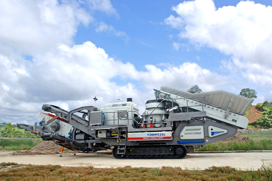
2. Crusher Section
3. Raw Material Storage & Pre-Homogenization
4. Raw Mill & Blending Silo
5. Preheater & Precalciner (Kiln Section)
6. Rotary Kiln (Clinker Production)
7. Clinker Cooler
8. Clinker Storage (Silo)
9. Cement Mill (Grinding Unit)
10. Cement Storage Silos
11. Packing & Dispatch Section
12. Utilities (Power, Water, Compressed Air, etc.)
—
2. Typical Cement Plant Layout
# (A) Raw Material Handling Area
– Located near the quarry to minimize transport distance.
– Includes:
– Limestone crusher (Primary & Secondary)
– Clay/Sand/Additive storage
– Stacker-reclaimer for pre-homogenization
# (B) Raw Grinding & Blending
– Raw mill (Ball Mill / VRM) for grinding raw materials.
– Blending silo for homogenization before kiln feed.
# (C) Kiln Section (Pyroprocessing)
– Preheater tower (4-6 stages) for heat recovery.
– Rotary kiln (~1400–1500°C for clinker formation).
– Clinker cooler (Grate or Planetary type).
# (D) Clinker & Cement Grinding
– Clinker storage silo.
– Cement mill (Ball Mill / VRM / Roller Press + Separator).
– Gypsum & additives storage.
.jpg) # (E) Packing & Dispatch
# (E) Packing & Dispatch
– Bulk loading silos.
– Packing machines for bagged cement.
– Truck/Railway loading area.
# (F) Utilities & Auxiliary Facilities
– Power substation / captive power plant.
– Compressed air system.
– Water treatment plant.
– Workshop & maintenance area.
– Administrative offices.
—
 3. Key Considerations in Layout Design
1. Material Flow Efficiency