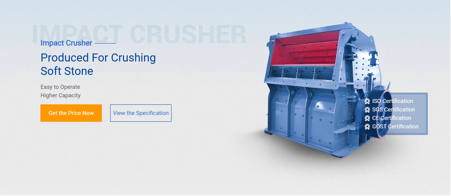
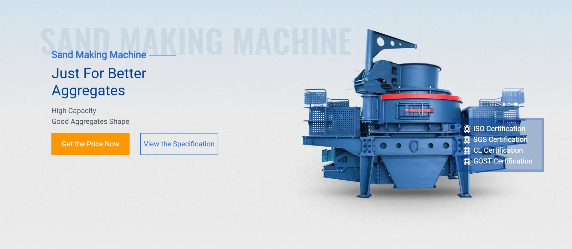
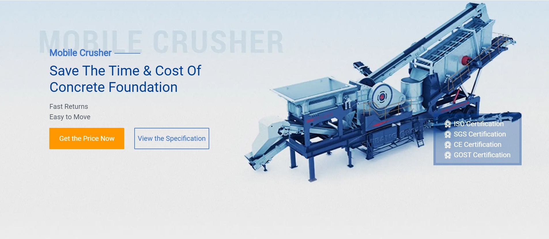
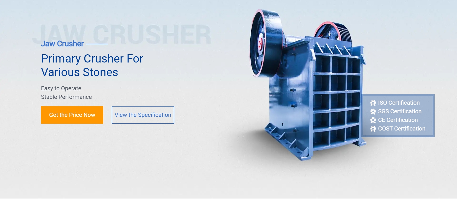
A hammer mill is a versatile machine used for grinding, crushing, and pulverizing various materials. The key objects (components) of a hammer mill include:
1. Feeding Mechanism (Hopper)
– Where raw material is fed into the mill.
– May include a feed chute or screw conveyor for controlled feeding.
2. Rotor Assembly
– The rotating shaft that holds the hammers.
– Driven by an electric motor or diesel engine via belts/pulleys.
3. Hammers (Beaters)
– Striking tools attached to the rotor.
– Made of hardened steel or manganese for durability.
– Shapes: Rectangular, T-shaped, or reversible for efficiency.
4. Screen (Sieve/Grate)
– Determines final particle size by controlling discharge.
– Different mesh sizes for coarse/fine grinding.
.jpg) 5. Crushing Chamber (Grinding Chamber)
5. Crushing Chamber (Grinding Chamber)
– Enclosed space where material is pulverized by hammers.
– Lined with wear-resistant plates to reduce abrasion.
6. Discharge Outlet
– Where processed material exits the mill (gravity or pneumatic).
7. Drive System (Motor & Pulleys/Belts) .jpg) – Powers the rotor at high speed (1,800–3,600 RPM).
– Powers the rotor at high speed (1,800–3,600 RPM).
8. Bearings & Shafts
– Support the rotor and ensure smooth rotation.
9. Frame/Housing
– Provides structural support and safety enclosure.
10. Control System (Optional)
– Speed regulators, safety switches, or automation controls.
Common Applications:
– Grain milling (corn, wheat)
– Biomass shredding (wood chips, straw)
– Recycling (e-waste, metal scraps)
– Pharmaceutical & food processing
Would you like details on a specific part or application?


